TL;DR
- Measure round-trip: Always count both outgoing and return conductors when calculating cable length.
- Target ≤3% drop: Use the voltage-drop formula and the AWG resistance table to select the right gauge.
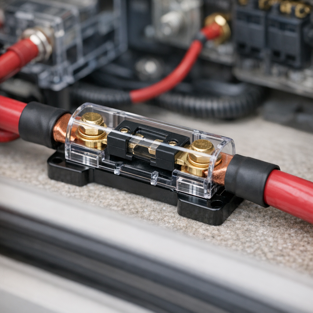
- Protect every run: Fuse or breaker must be rated to the cable ampacity, not the load.
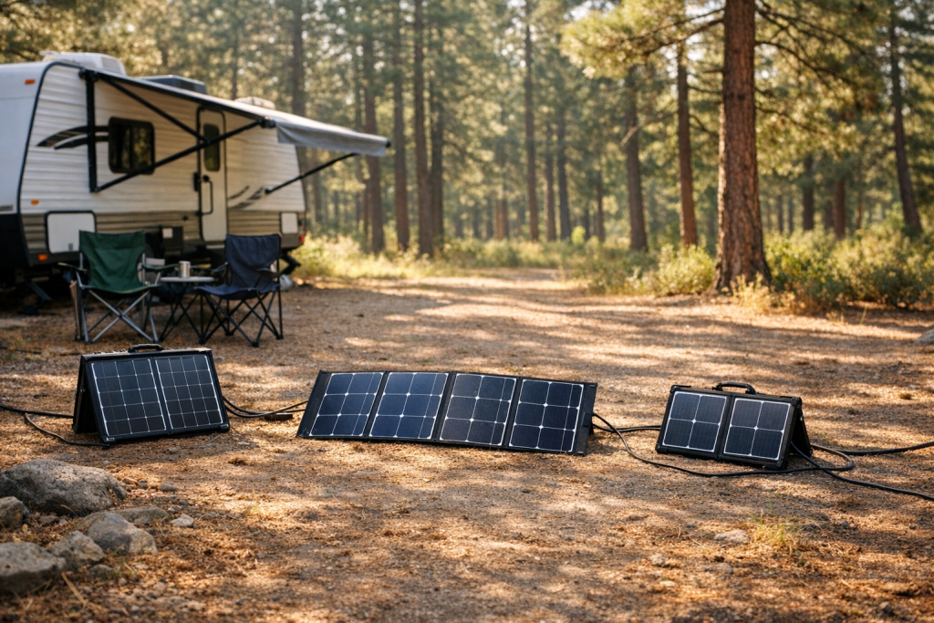
Introduction to RV solar cable sizing
A 25-foot panel-to-controller run carrying 20 A on undersized 14 AWG copper loses nearly 2.5 V—over 20 percent of a 12 V battery bank . That lost voltage is lost watts, every hour of every sunny day. Correct cable sizing eliminates this silent drain and protects against overheating.
The process requires only three numbers: current, round-trip distance, and the resistance per unit length of the wire gauge you select.
Why Cable Sizing Matters in RV Solar Systems
DC circuits are far more sensitive to voltage drop than the AC wiring in a house. At 12 V nominal, even a fraction of a volt represents a meaningful percentage of total system voltage. A cable that would be perfectly adequate in a 120 V AC branch circuit can become a serious bottleneck in a low-voltage DC solar installation. The energy lost in the cable converts directly to heat, reducing charging efficiency and, in extreme cases, creating a fire hazard inside the confined spaces of an RV.
Voltage drop also affects charge controller behavior. An MPPT controller expects a certain input voltage window from the panels; excessive line loss can push the arriving voltage below the controller’s minimum operating threshold, especially during low-light conditions when panel output is already marginal. For more on controller selection, see MPPT charge controllers.
Undersized cables waste money twice: once in the energy they squander and again when they need to be replaced after overheating damages insulation.
Step-by-Step Cable Sizing
Follow these four steps every time you plan a new run or modify an existing one. The method works for panel-to-controller, controller-to-battery, and battery-to-inverter segments alike.
- Determine total current (A). For panel-to-controller runs, use the short-circuit current (Isc) of the panel or parallel-connected panel array, not the maximum power current (Imp). Isc is the worst-case current the cable must carry. For controller-to-battery runs, use the charge controller’s rated output current. If you are sizing cable for an inverter feed, divide the inverter’s maximum continuous wattage by the nominal battery voltage and add 10–15 percent for inefficiency. For a 2000 W inverter on a 12 V bank at roughly 88 percent efficiency, that is approximately (2000 ÷ 12) ÷ 0.88 ≈ 189 A.
- Measure the ROUND-TRIP cable length (ft). This is the single most common mistake in RV solar wiring. Current must travel from the source to the load and back. Measure the physical one-way distance along the actual routing path—over cabinets, through conduit, along the frame rail—then multiply by two. A panel mounted 15 feet from the charge controller requires a 30-foot round-trip calculation. Add an extra foot or two for termination slack at each end.
- Apply the voltage-drop formula. Using the round-trip length, the current, and the resistance per 1,000 feet for the candidate wire gauge, calculate the expected voltage drop. Compare the result against your target—typically 3 percent or less of nominal system voltage.
- Select the correct AWG from the resistance table. If the calculated drop exceeds your target, move to the next larger (lower AWG number) wire size and recalculate. Repeat until the drop falls within the acceptable range. Then verify that the chosen gauge also meets the ampacity requirement for the expected current and ambient temperature.
For a deeper look at how cable sizing interacts with inverter loads, see RV inverter sizing.
Voltage-Drop Formula
The factor of 2 accounts for the round-trip path of the current—positive conductor out, negative conductor back. “Length” in this formula is the one-way physical distance; the formula doubles it internally. Some references fold the factor of 2 into the length term and ask you to enter the total round-trip distance directly. Either approach yields the same answer, but you must be consistent. Throughout this article, “Length” always means the one-way measurement.
The resistance values used are for solid or stranded uncoated copper at 20 °C (68 °F). At higher temperatures, copper resistance increases by approximately 0.393 percent per degree Celsius. In a sun-baked RV roof conduit that might reach 60 °C, resistance is roughly 16 percent higher than the 20 °C table value. A practical way to handle this is to target a 2.5 percent drop at 20 °C values, leaving headroom for thermal rise.
Quick Numeric Check
Suppose you have a 15-foot one-way run carrying 10 A on 10 AWG copper (1.02 Ω/1000 ft). The drop is (2 × 15 × 10 × 1.02) / 1000 = 0.306 V. On a 12 V system that is 2.55 percent—within the 3 percent guideline. On a 24 V system the same drop is only 1.28 percent, illustrating why higher-voltage battery banks are more forgiving of cable length.
Understanding the ≤ 3 Percent Rule
The 3 percent voltage-drop guideline is not a legal code for RV solar; it is an engineering best practice drawn from the National Electrical Code’s recommendation for branch circuits (NEC 210.19 Informational Note No. 4). In a 12 V system, 3 percent equals 0.36 V. In a 24 V system, 3 percent equals 0.72 V—twice the absolute voltage budget for the same percentage.
Some installers target 2 percent for long or critical runs, especially the panel-to-controller segment where every lost volt directly reduces harvest. The controller-to-battery run is shorter in most RVs and easier to keep under 1 percent.
Never combine the drops of two separate segments and call the total “3 percent.” Each segment should meet the target independently. A 2 percent drop from panels to controller plus a 2 percent drop from controller to battery is a cumulative 4 percent system loss—unacceptable for a 12 V installation where you are already working with thin voltage margins.
Worked Examples
Example 1: 12 V System — Panels to Charge Controller
A Class B camper van has two 200 W panels wired in parallel on the roof. Each panel has an Isc of 6.2 A, so the combined short-circuit current is 12.4 A. The one-way cable distance from the roof combiner box, down through the refrigerator cabinet, and to the charge controller is 18 feet.
Target maximum drop: 12 V × 0.03 = 0.36 V.
Try 10 AWG copper (1.02 Ω/1000 ft):
That is 0.455 / 12 = 3.79 percent—over the limit.
Move up to 8 AWG copper (0.641 Ω/1000 ft):
The drop is 0.286 / 12 = 2.38 percent. Within the 3 percent target with room for temperature derating. Select 8 AWG for this run.
Verify ampacity: 8 AWG copper in 90 °C-rated insulation (THWN-2 or equivalent) is rated for 55 A in free air. At 12.4 A, the cable is well within its thermal limit. A 15 A fuse at the panel combiner box protects this conductor.
Example 2: 24 V System — Panels to Charge Controller
A fifth-wheel trailer runs a 24 V battery bank. Four 200 W panels are configured as two series strings of two panels each, with the two strings wired in parallel. Each string’s Isc is 6.2 A, so total array Isc is 12.4 A. The one-way cable run from the roof junction box to the controller inside a basement compartment is 30 feet.
Target maximum drop: 24 V × 0.03 = 0.72 V.
Try 10 AWG copper (1.02 Ω/1000 ft):
That is 0.758 / 24 = 3.16 percent—just over the line.
Move up to 8 AWG copper (0.641 Ω/1000 ft):
The drop is 0.476 / 24 = 1.98 percent. 8 AWG handles this 30-foot run at 24 V comfortably, whereas the same gauge barely passed for an 18-foot run at 12 V. This demonstrates the practical advantage of a higher-voltage battery bank: you can use the same wire over longer distances.
Fuse this run at 15 A, placed within 7 inches of the positive bus at the combiner box.
Example 3: Battery to Inverter (12 V, High Current)
A 2000 W pure-sine inverter on a 12 V bank draws up to approximately 189 A at full load (assuming inverter efficiency around 88 percent). The one-way cable distance from the battery bank to the inverter is only 4 feet, but the current is enormous.
Target maximum drop: 12 V × 0.03 = 0.36 V.
Try 2/0 AWG copper (0.0795 Ω/1000 ft):
That is 0.120 / 12 = 1.00 percent—well within limits. 2/0 AWG fine-stranded copper with a 200 A Class-T fuse is a standard and safe choice for this application. Even a one-foot increase in cable length at these currents adds measurable loss, so keep inverter-to-battery runs as short as physically possible.
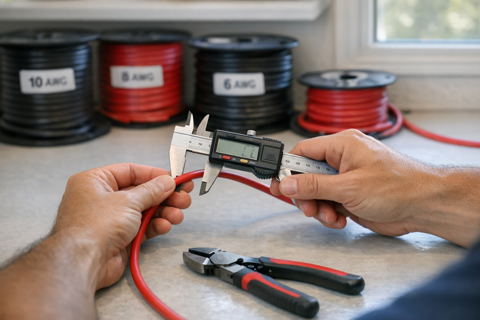
AWG to mm² and Resistance Table
The table below lists common wire gauges used in RV solar installations. Resistance values are for uncoated (bare) copper at 20 °C. Stranded wire of the same AWG has a marginally higher resistance than solid wire (typically 1–2 percent) due to air gaps between strands, but the difference is negligible for sizing purposes.
| AWG | Cross-Section (mm²) | Resistance (Ω/1000 ft at 20 °C) | Resistance (Ω/km at 20 °C) | Typical RV Solar Use |
|---|---|---|---|---|
| 14 | 2.08 | 2.525 | 8.282 | Branch circuits, small panel leads (< 5 A) |
| 12 | 3.31 | 1.588 | 5.211 | Short panel runs, controller to battery (low current) |
| 10 | 5.26 | 1.018 | 3.340 | Common panel-to-controller gauge |
| 8 | 8.37 | 0.641 | 2.103 | Longer panel runs, moderate current |
| 6 | 13.30 | 0.403 | 1.322 | Controller to battery, mid-size inverters |
| 4 | 21.15 | 0.253 | 0.830 | High-current battery runs, small inverter feeds |
| 2 | 33.62 | 0.159 | 0.522 | Inverter feeds up to ~100 A |
| 1/0 (0) | 53.49 | 0.100 | 0.328 | Large inverter feeds, bus bars |
| 2/0 (00) | 67.43 | 0.0795 | 0.261 | 2000 W+ inverter feeds |
| 4/0 (0000) | 107.2 | 0.0500 | 0.164 | Very high-current applications, 3000 W+ inverters on 12 V |
Important: Always keep total voltage drop at or below 3 percent of nominal system voltage for each individual cable segment. At elevated temperatures (above 30 °C / 86 °F), copper resistance rises. If your cables pass through engine compartments or sun-exposed conduit, consider upsizing one AWG or targeting a 2 percent drop at 20 °C table values to maintain the 3 percent limit under real-world thermal conditions.
Installation Tips
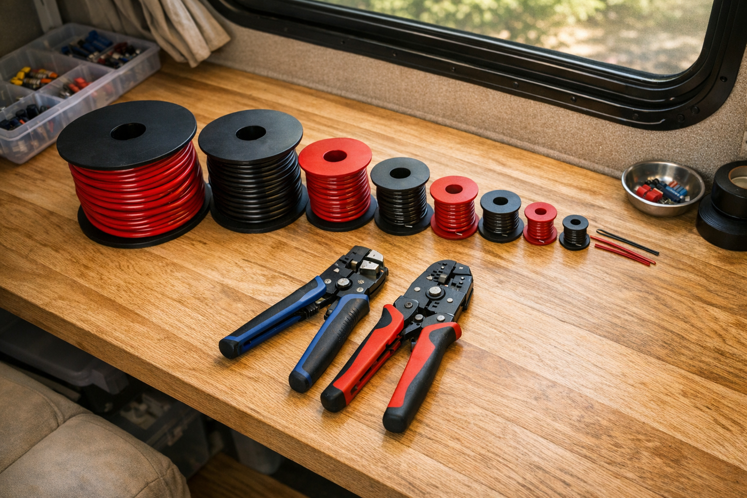
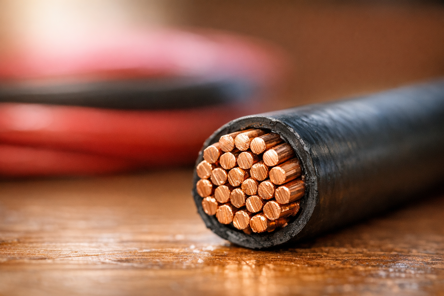
- Use fine-stranded cable for flexibility. RV environments involve vibration, tight bends around cabinet corners, and repeated thermal cycling. Fine-stranded (Class K or Class M) copper cable resists fatigue cracking far better than solid or coarse-stranded wire. Marine-grade tinned copper is even better—the tin coating prevents corrosion of individual strands, which is especially important in coastal or humid climates.
- Crimp, don’t solder, for power connections. Solder wicks up the strands and creates a rigid zone prone to fracture under vibration. Use hydraulic or ratcheting crimpers with appropriately sized copper lugs. After crimping, apply adhesive-lined heat shrink tubing over the lug barrel to seal out moisture.
- Support cables every 18 inches. Unsupported cables sag, chafe against sharp edges, and transfer vibration stress to terminal connections. Use adhesive-backed cable clamps or P-clips with rubber liners. Avoid zip ties directly on insulation—they can cut through over time.
- Separate positive and negative runs where possible. Running both conductors in the same conduit or loom is acceptable, but if a chafe point develops, having them in separate protective sleeves reduces the chance of a dead short. At minimum, use split-loom tubing wherever cables pass through bulkheads or over frame members.
- Label every cable at both ends. Use printed heat-shrink labels or permanent cable tags. In an RV with multiple circuits—solar, alternator charging, shore power—unlabeled cables become a troubleshooting nightmare and a safety risk during emergency disconnection.
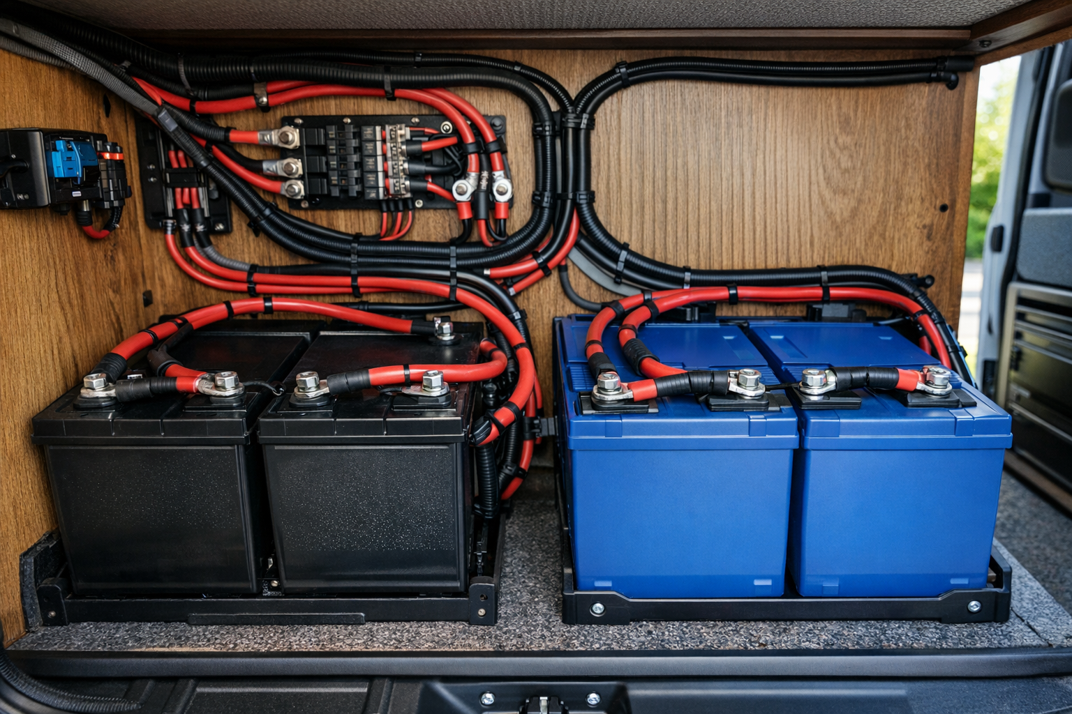
- Torque terminal connections to spec. Loose connections are the leading cause of DC electrical fires. Bus bar studs, battery terminals, and fuse holder bolts all have torque specifications. Use a torque wrench—not “good and tight.” Re-check connections after the first 500 miles of travel, as vibration can loosen fasteners.
- Install a battery disconnect switch. A master disconnect between the battery bank and the rest of the system allows you to de-energize all DC circuits for maintenance or in an emergency. Place it in an accessible location and ensure it is rated for the full system current.
- Account for real-world battery capacity. When calculating how long your system can run on stored energy, never assume the chemistry-rated usable capacity. LiFePO4 batteries typically offer 80–90 percent usable depth of discharge. Lead-acid batteries should not be discharged below 50 percent regularly. Size your cables—and your expectations—around the actual usable energy, not the nameplate rating.
Safety & Common Mistakes
- Size fuses and breakers to the cable ampacity, not the load — undersized protection cannot prevent overheating.
- Always measure round-trip length; ignoring the return conductor undersizes the cable.
- Derate ampacity for bundled runs and high-ambient temperatures.
- Use properly crimped and heat-shrunk terminals — loose connections create hot spots.
- Route cables away from heat sources and sharp edges; secure every 18 in (45 cm).
FAQs
- What happens if I exceed the 3 percent voltage-drop limit? The system still functions, but you lose real energy. On a 12 V system, a 5 percent drop means 0.6 V lost in the cable. Over a 400 W array producing for 5 peak sun hours daily, that can translate to roughly 15–20 Wh per day of wasted energy—heat generated in the wire instead of stored in the battery. Over a season, the cumulative loss can equal the cost of properly sized cable.
- Should I use the same gauge for positive and negative conductors? Yes. Both conductors carry the same current and contribute equally to the round-trip resistance. Using a smaller gauge for the negative (ground return) conductor does not save meaningful cost and creates an asymmetric circuit where the thinner wire becomes the thermal weak point.
- How do I size cable for panels wired in series versus parallel? Series wiring increases voltage while current stays the same as a single panel’s Isc. Parallel wiring keeps voltage the same but adds the Isc values of each string. Higher voltage (series) means lower current for the same total wattage, which allows smaller cable or longer runs. This is why series configurations are generally preferred for rooftop-to-controller runs in larger RVs with long cable distances.
- Is there a maximum cable length for RV solar? There is no hard maximum—only the practical limit imposed by voltage drop and cost. With large enough cable, you can run any distance. For most RVs, keeping panel-to-controller runs under 30 feet one-way with appropriately sized cable (8 AWG or larger for 12 V systems) avoids excessive drop. If your run exceeds 40 feet on a 12 V system, seriously consider moving to a 24 V battery bank or relocating the charge controller closer to the panels.
- Do MC4 connectors add significant resistance? A properly crimped MC4 connection adds less than 0.5 mΩ of contact resistance—negligible in the context of a typical cable run. However, corroded, loose, or poorly crimped MC4 connectors can develop resistance of 100 mΩ or more, creating localized hot spots. Inspect rooftop connectors annually and replace any that show discoloration or feel warm during operation.
Conclusion
Sizing RV solar cable correctly comes down to four concrete decisions. First, measure the one-way cable distance along the actual routing path and recognize that the formula accounts for the round-trip by doubling it. Second, set your voltage-drop target at 3 percent or less of nominal system voltage—0.36 V for 12 V systems, 0.72 V for 24 V systems—applied independently to each cable segment. Third, select the AWG that keeps the calculated drop within that target: for a typical 12 V van with 12 A of panel current and an 18-foot one-way run, that means 8 AWG copper; for a 24 V fifth-wheel with the same current over 30 feet, 8 AWG also works but with a much more comfortable margin. Fourth, fuse every positive conductor at or below the wire’s ampacity and above 125 percent of the continuous load—a 15 A fuse for the panel runs in our examples, a 200 A Class-T fuse for the inverter feed.
Get these four numbers right, use quality copper cable with appropriate insulation ratings, and your RV solar system will deliver its full potential to the battery bank with minimal loss and maximum safety.