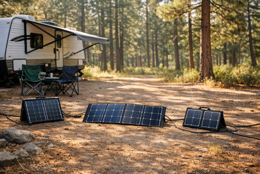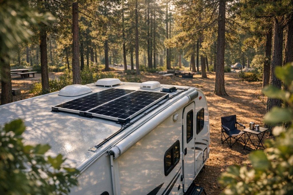
You just mounted four 100-watt panels on the roof of your Class C motorhome. The charge controller sits inside a cabinet above the rear axle, roughly 20 feet of wire away from the combiner box on the roof. You’re running a 12-volt battery bank. The panels are wired in parallel, producing a combined short-circuit current of about 24 amps. You grab a spool of 10 AWG wire from the hardware store because “it handles 30 amps.” Three months later, your batteries never seem to reach full charge, and the wire feeding through the refrigerator vent feels warm to the touch on sunny afternoons. The problem isn’t your panels or your batteries — it’s the cable between them. At 12 V, a mere 0.36 V loss eats 3% of your system voltage, and that 10 AWG wire over a 40-foot round trip is dropping closer to a full volt. You’re bleeding roughly 8% of your harvest into heat before a single electron reaches the battery.
This guide walks through real RV scenarios — from a minimalist two-panel van build to a high-output 48 V system on a fifth-wheel — and shows you how to size every cable so you keep voltage drop under control, pass NEC requirements, and actually capture the solar energy you paid for.
TL;DR
- Measure round-trip: Always count both outgoing and return conductors when calculating cable length.
- Target ≤3% drop: Use the voltage-drop formula and the AWG resistance table to select the right gauge.
- Protect every run: Fuse or breaker must be rated to the cable ampacity, not the load.
Common Scenarios & Quick Picks
The table below covers six configurations RV owners encounter most often. “Round-trip” means the total conductor length: positive run plus negative return. Current values already include the NEC 690.8 factor of 1.56× the panel short-circuit current (Isc), which accounts for both irradiance overage (1.25×) and continuous-load treatment (1.25×). The maximum voltage drop target is 3% of nominal system voltage — the widely accepted ceiling for battery-charging circuits.
| Scenario | Run (ft, round-trip) | Design Current (A) | Max Drop (V / %) | Recommended AWG |
|---|---|---|---|---|
| 200 W / 12 V — short run (camper van, panels to controller through roof) | 20 | 16.4 | 0.36 V / 3% | 6 AWG |
| 400 W / 12 V — medium run (Class C, roof to rear cabinet) | 40 | 32.8 | 0.36 V / 3% | 2 AWG |
| 400 W / 24 V — medium run (travel trailer, roof to under-bed bank) | 40 | 16.4 | 0.72 V / 3% | 8 AWG |
| 800 W / 24 V — long run (fifth-wheel, roof to front basement) | 60 | 32.8 | 0.72 V / 3% | 4 AWG |
| 800 W / 48 V — long run (large motorhome, roof to engine-bay bank) | 60 | 16.4 | 1.44 V / 3% | 10 AWG |
| 1200 W / 48 V — very long run (bus conversion, rear panels to front bank) | 80 | 24.6 | 1.44 V / 3% | 8 AWG |
Notice the pattern: doubling system voltage cuts required current in half for the same wattage, which lets you use dramatically thinner (and cheaper, lighter) cable. This is why serious off-grid RV builders gravitate toward 24 V or 48 V battery banks.
How to Estimate Current
Start with the short-circuit current (Isc) printed on each panel’s datasheet — not the maximum power current (Imp). Isc represents the worst-case current the panel can push, and NEC Article 690.8 requires you to multiply it by 1.56 to arrive at the design current for conductor sizing.
Why 1.56×? It’s two safety factors stacked: 1.25 for irradiance conditions that can exceed Standard Test Conditions (reflected light off snow, cool clear mornings at altitude), and another 1.25 because solar circuits are treated as continuous loads — they can run at full output for more than three hours straight.
For panels wired in parallel, add the Isc values together before applying the multiplier. For panels wired in series, the current stays at a single panel’s Isc (voltage adds instead).
| Panel Rating | Typical Isc | Panels in Parallel | Combined Isc | Design Current (×1.56) |
|---|---|---|---|---|
| 100 W / 12 V | ~5.8 A | 2 | 11.6 A | 18.1 A |
| 100 W / 12 V | ~5.8 A | 4 | 23.2 A | 36.2 A |
| 200 W / 24 V | ~5.5 A | 2 | 11.0 A | 17.2 A |
| 200 W / 24 V | ~5.5 A | 4 | 22.0 A | 34.3 A |
| 400 W / 48 V | ~5.3 A | 3 | 15.9 A | 24.8 A |
If you can’t find the Isc on the label, a conservative estimate is panel wattage divided by the nominal voltage, then add 20%. For a 200 W panel at 12 V nominal: 200 ÷ 12 = 16.7 A, plus 20% ≈ 20 A. Then multiply by 1.25 for continuous duty to get roughly 25 A design current. This is less precise than using the actual Isc, but it keeps you in safe territory.
Voltage-Drop Formula
Keep total drop at or below 3% of system voltage for any single DC circuit segment (panels to controller, controller to battery bank). The combined drop across all segments should stay under 5%.
| System Voltage | 3% Drop Limit |
|---|---|
| 12 V | 0.36 V |
| 24 V | 0.72 V |
| 48 V | 1.44 V |
The factor of 2 in the formula accounts for the round trip — current flows out on the positive conductor and returns on the negative. If you’ve already measured the total round-trip length, replace 2 × Length with your measured total and use: (Total Round-Trip Length × Current × Resistance) / 1000.
The “Resistance” value is the DC resistance of copper wire at a given gauge, expressed in ohms per 1,000 feet. Temperature matters: published resistance figures assume 25 °C (77 °F). At 50 °C (122 °F) — realistic inside conduit on a sun-baked RV roof — resistance increases roughly 10%. In hot environments, either derate the wire’s ampacity or step up one gauge.
Worked Examples
12 V Example — 400 W Array, 20-Foot One-Way Run
Setup: Four 100 W panels wired in parallel on a Class B van roof. Isc per panel = 5.8 A. Charge controller mounted directly below the roof entry point. One-way cable distance = 20 feet.
Step 1 — Design current:
Design current = 23.2 A × 1.56 = 36.2 A
Step 2 — Allowable voltage drop:
Step 3 — Rearrange the formula to find maximum allowable resistance:
Max R = (0.36 × 1000) / (2 × 20 × 36.2)
Max R = 360 / 1448
Max R = 0.249 Ω/1000 ft
Step 4 — Select wire gauge: Consulting the resistance table below, 4 AWG copper has a resistance of 0.249 Ω/1000 ft — right at the limit. To provide margin (especially in a hot roof cavity), choose 2 AWG at 0.156 Ω/1000 ft.
Step 5 — Verify:
= 1448 × 0.156 / 1000
= 0.226 V
= 1.88% of 12 V ✓
A 1.88% drop is well within the 3% target, leaving headroom for the controller-to-battery segment.
24 V Example — 800 W Array, 30-Foot One-Way Run
Setup: Four 200 W panels wired in two series strings of two, then the strings paralleled (2S2P). Each panel Isc = 5.5 A. Two parallel strings yield a combined Isc of 11.0 A. The charge controller sits in a basement compartment 30 feet from the roof combiner.
Step 1 — Design current:
Design current = 11.0 A × 1.56 = 17.2 A
Step 2 — Allowable voltage drop:
Step 3 — Find maximum resistance:
Max R = 720 / 1032
Max R = 0.698 Ω/1000 ft
Step 4 — Select wire gauge: 8 AWG copper has a resistance of 0.628 Ω/1000 ft, which is under the 0.698 limit. Its standard ampacity of 50 A in free air (NEC Table 310.16) comfortably exceeds 17.2 A. Choose 8 AWG.
Step 5 — Verify:
= 1032 × 0.628 / 1000
= 0.648 V
= 2.70% of 24 V ✓
At 2.70%, you’re under the ceiling with a small buffer. If the cable passes through hot areas (engine bay, attic space above 40 °C), stepping up to 6 AWG at 0.395 Ω/1000 ft drops the loss to 1.63%.
AWG to mm² and Resistance Table
This table lists copper conductor properties at 25 °C (77 °F). For aluminum conductors, multiply resistance by approximately 1.6 — or step up two AWG sizes from the copper recommendation. In RV applications, copper is strongly preferred: it resists vibration-induced fatigue better, has a lower thermal expansion coefficient, and doesn’t require anti-oxidant compound at every termination the way aluminum does.
| AWG | mm² | Ω/1000 ft (copper, 25 °C) | Ω/km (copper, 25 °C) | Ampacity (free air, 30 °C) |
|---|---|---|---|---|
| 14 | 2.08 | 2.525 | 8.282 | 20 A |
| 12 | 3.31 | 1.588 | 5.209 | 25 A |
| 10 | 5.26 | 0.999 | 3.277 | 35 A |
| 8 | 8.37 | 0.628 | 2.061 | 50 A |
| 6 | 13.30 | 0.395 | 1.296 | 65 A |
| 4 | 21.15 | 0.249 | 0.817 | 85 A |
| 2 | 33.62 | 0.156 | 0.512 | 115 A |
| 1/0 (0) | 53.49 | 0.098 | 0.322 | 150 A |
| 2/0 (00) | 67.43 | 0.078 | 0.256 | 175 A |
| 4/0 (0000) | 107.2 | 0.049 | 0.161 | 230 A |
The “Ω/1000 ft” column is what you plug directly into the voltage-drop formula. If you’re working in metric, use the “Ω/km” column and convert your cable length to kilometers. The ampacity column represents the maximum continuous current in free air at 30 °C ambient. In bundled conduit or at elevated temperatures, apply NEC derating factors — typically 80% for three or more current-carrying conductors in a conduit, and additional reductions above 30 °C ambient.
Safety & Common Mistakes
- Size fuses and breakers to the cable ampacity, not the load — undersized protection cannot prevent overheating.
- Always measure round-trip length; ignoring the return conductor undersizes the cable.
- Derate ampacity for bundled runs and high-ambient temperatures.
- Use properly crimped and heat-shrunk terminals — loose connections create hot spots.
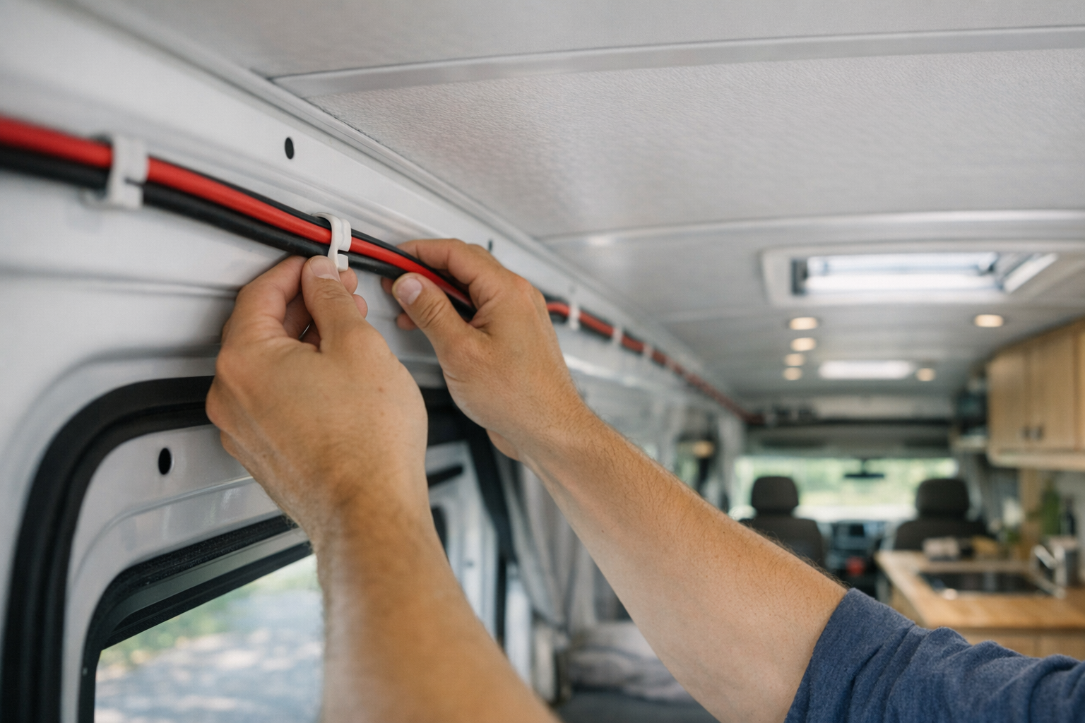
- Route cables away from heat sources and sharp edges; secure every 18 in (45 cm).
FAQs
- What if my cable run is longer than planned? Recalculate using the actual round-trip length. Even an extra 10 feet can push a borderline gauge over the 3% drop threshold, especially at 12 V. If you discover the issue after installation, the most practical fix is to upsize the cable gauge for the entire run — splicing in a thicker section partway doesn’t help, because the thinner segment still drops the same voltage across its length. Alternatively, if your charge controller supports it, reconfiguring panels from parallel to series raises the circuit voltage and proportionally reduces current and voltage drop without changing a single wire.
- Can I mix cable sizes on one circuit segment? Avoid it. The thinnest section limits the current-carrying capacity of the entire run and creates a localized hot spot where the wire narrows. The fuse must be sized to protect the smallest conductor, which may mean it trips during normal operation if the rest of the circuit was designed for a larger gauge. If you must extend a run, use wire of the same gauge or larger, with a properly rated junction box and marine-grade butt connectors or terminal blocks.
- Does ambient temperature change my AWG choice? Yes. Higher temperatures increase copper’s resistance (roughly 0.4% per degree Celsius above 25 °C) and simultaneously reduce the wire’s safe ampacity. In a rooftop conduit at 60 °C, a 90 °C-rated conductor loses about 29% of its base ampacity. This double penalty — more resistance causing more drop, and less headroom before overheating — means you should step up at least one AWG size for any run through consistently hot environments like engine compartments, attic spaces above the ceiling, or sun-exposed exterior conduit.
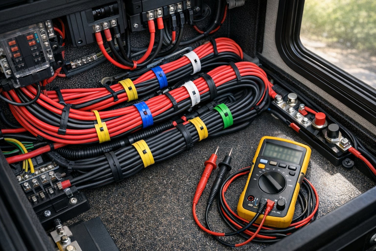
- How do I verify my sizing after installation? Measure the voltage at both ends of the cable under full load with a multimeter. Do this at peak solar production (midday, clear sky, panels clean). Read the voltage at the panel combiner output and at the charge controller input simultaneously if possible, or in quick succession. The difference should match or be less than your formula estimate. If the measured drop exceeds your 3% target, check for corroded terminals, loose crimps, or undersized connectors — these add resistance the formula doesn’t account for. A thermal camera or infrared thermometer pointed at connections and cable runs can reveal hot spots that indicate high-resistance faults.
- Why is the NEC multiplier 1.56× instead of just 1.25×? NEC 690.8 applies two separate 1.25 factors that multiply together: 1.25 × 1.25 = 1.5625, rounded to 1.56. The first factor accounts for the fact that solar irradiance can exceed the 1,000 W/m² Standard Test Conditions — reflected light from snow, water, or light-colored surfaces can push actual irradiance 20–25% higher. The second factor treats the PV circuit as a continuous load (operating at maximum current for three or more hours), which requires conductors and overcurrent devices to be rated at 125% of the expected current. Both conditions are realistic in RV use: you might be parked on a snow-covered mountain pass with panels producing well above nameplate current for an entire afternoon.
- Should I size the charge-controller-to-battery cable differently? Yes. An MPPT charge controllers converts higher panel voltage to lower battery voltage, which means the output current to the battery can be significantly higher than the input current from the panels. For example, a 48 V / 800 W array feeding an MPPT controller charging a 12 V battery bank will output roughly 60–65 A on the battery side. Size the controller-to-battery cable for the controller’s maximum rated output current multiplied by 1.25 for continuous duty, and keep the run as short as physically possible — ideally under 6 feet round trip. This segment often requires the heaviest cable in the entire system.
Conclusion
Correct RV solar cable sizing comes down to four decisions made in sequence. First, measure the actual round-trip conductor length — positive run plus negative return, including every bend, drop, and detour, with 10–15% added for slack. Second, set your voltage-drop target: 3% per circuit segment (panels to controller, controller to batteries), 5% maximum across the entire system. Third, calculate the correct AWG using the voltage-drop formula — (2 × Length × Current × Resistance per 1000 ft) / 1000 — making sure the result stays under your target and the wire’s ampacity exceeds your NEC-adjusted design current of 1.56× Isc. Fourth, install a DC-rated fuse or breaker at the next standard size above the design current, confirmed to be at or below the conductor’s derated ampacity, mounted within 18 inches of the power source.
At 12 V, you have only 0.36 V of headroom before you’ve lost 3% of your system voltage. That razor-thin margin is why 12 V systems demand heavy, expensive cable for anything beyond a very short run — and why upgrading to 24 V or 48 V is the single most effective way to reduce cable cost, weight, and losses in a serious RV solar installation. Run the numbers before you buy the wire. The formula takes 60 seconds. The regret of undersized cable lasts the life of the system.