TL;DR
- Takeaway 1: Follow each step carefully from start to finish.
- Takeaway 2: Gather all tools and materials before starting.
- Takeaway 3: Test your work after each major step to catch issues early.
A single 3,000-watt pure-sine inverter on a 12-volt bank can pull 250 amps continuous and spike past 500 amps on startup—yet many RV builders wire it with cable rated for only 150 amps. The inverter is the highest-current device in any RV solar system, so every wiring decision should radiate outward from it. This guide sizes each cable segment from solar panels to charge controller, charge controller to battery, and battery to inverter, accounting for surge loads, temperature derating, cable bundling, and voltage-drop budgets that keep your system efficient and safe.
Why Size From the Inverter Backward
Most guides start at the solar panel and work down. That approach buries the hardest engineering problem—the battery-to-inverter run—at the end, after you’ve already committed to a battery location and conduit path.
Inverter cables carry the highest current in the system by a wide margin. On a 12-volt bank, every 100 watts of AC output demands roughly 8.3 amps of DC input (before efficiency losses push it closer to 9.5–10 A). A 2,000 W load therefore requires about 190–200 A of continuous DC current, and motor-driven appliances like air conditioners or compressor fridges can demand two to three times their rated wattage during the first half-second of startup.
If you size the inverter cable first, you lock in the maximum allowable distance between battery and inverter, choose a realistic cable gauge, and then route everything else to fit.
Paths You Must Size
Every RV solar installation has three distinct cable segments, each with its own voltage, current profile, and protection requirements:
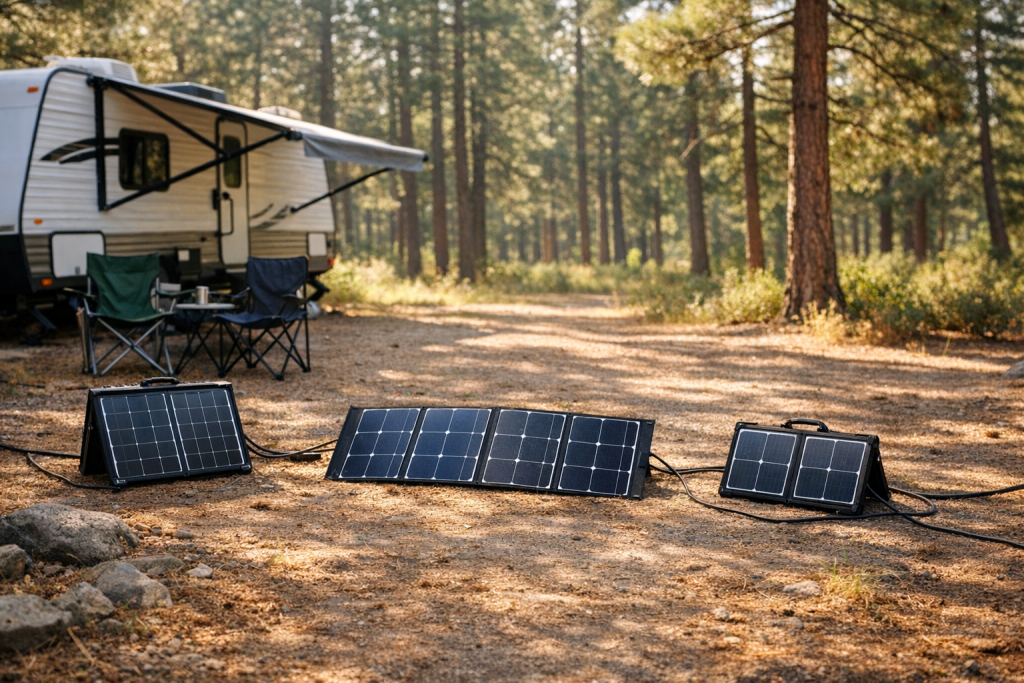
- Panels → MPPT charge controller guide: Carries the panel’s short-circuit current (Isc) at the panel’s open-circuit voltage (Voc). Current is relatively low; voltage is high (often 40–150 V depending on series strings). Wire gauge is usually modest, but voltage drop matters for efficiency.
- MPPT → Battery Bank: The charge controller steps voltage down and current up. On a 12 V system with a 60 A MPPT controller, this segment can carry the full rated output of the controller. Cable runs are usually short but must handle sustained high current during peak solar hours.
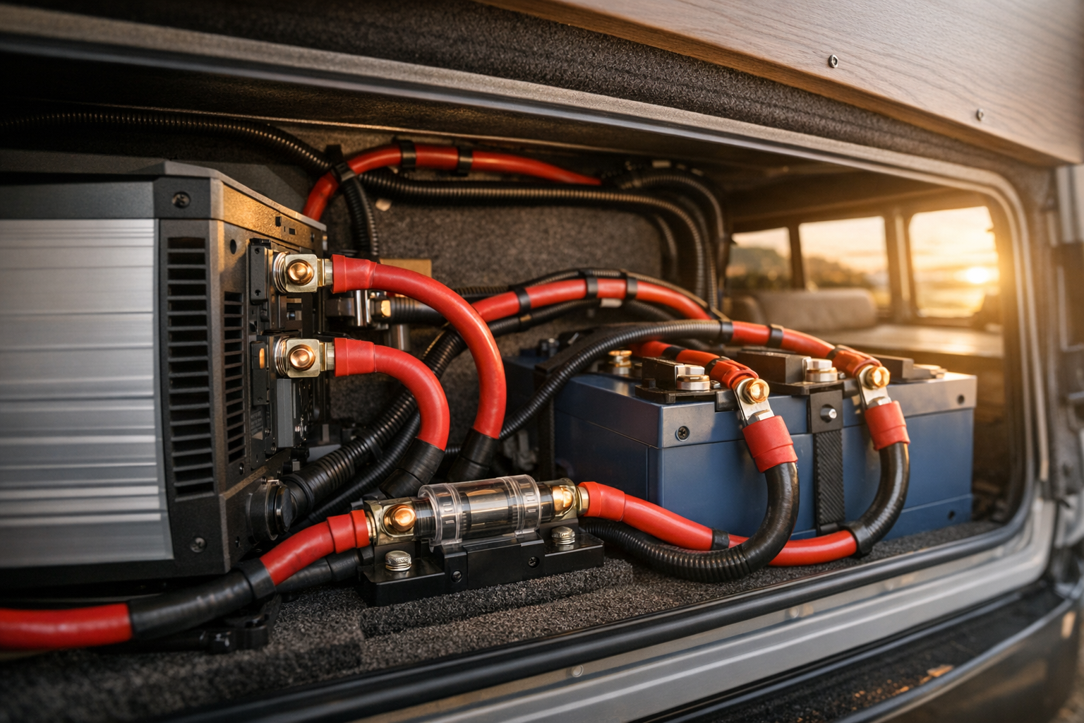
- Battery → Inverter: The highest-current segment. Must be sized for the inverter’s continuous rating and its surge rating, with derating applied for temperature and cable bundling. Undersizing here causes the most damage—melted insulation, voltage sag that triggers inverter low-voltage shutdowns, or worse.
Core Sizing Formula
For any DC cable segment, the minimum conductor cross-section is governed by allowable voltage drop:
Amin = (2 × L × I × ρ) / Vdrop
Where:
- Amin = minimum conductor cross-section in mm²
- L = one-way cable length in meters
- I = current in amps
- ρ = resistivity of copper ≈ 0.0175 Ω·mm²/m at 25 °C
- Vdrop = maximum allowable voltage drop in volts
The factor of 2 accounts for the positive and negative conductors (round-trip distance).
If you’re working in AWG and feet, use the resistance-per-thousand-feet values from the table below and apply Ohm’s law directly: Vdrop = I × Rtotal, where Rtotal = (2 × Lft / 1000) × Ω/1000 ft.
Voltage-Drop Budgets
Industry best practice allocates no more than 2–3 % total voltage drop across the entire DC system. A practical split:
| Segment | Recommended Max Drop | 12 V System (volts) | 24 V System (volts) |
|---|---|---|---|
| Panels → Controller | 1–2 % | 0.12–0.24 V (at ~18 V Vmp, 0.18–0.36 V) | 0.24–0.48 V (at ~36 V Vmp, 0.36–0.72 V) |
| Controller → Battery | 0.5–1 % | 0.06–0.12 V | 0.12–0.24 V |
| Battery → Inverter | 1–1.5 % | 0.12–0.18 V | 0.24–0.36 V |
On a 12 V system, every tenth of a volt matters. A 0.5 V drop on the battery-to-inverter run at 200 A wastes 100 watts as heat in the cable—heat that further increases resistance and compounds the problem.
Derating Factors
The ampacity printed on a cable spool assumes a single conductor in free air at 30 °C (86 °F). Real RV installations rarely meet those conditions.
Temperature Derating
Copper’s resistance rises approximately 0.393 % per degree Celsius above 20 °C. An engine bay or roof-mounted conduit in the Arizona sun can easily reach 50–60 °C. At 50 °C, multiply the cable’s base ampacity by a temperature correction factor—typically 0.82 for 90 °C-rated insulation (THWN-2) or 0.71 for 75 °C-rated insulation (THWN). Always check NEC Table 310.15(B)(1) correction factors or the equivalent table in your jurisdiction.
Practical rule: if your cables run through an area that regularly exceeds 40 °C, go up one AWG size from what the voltage-drop calculation alone suggests.
Bundling Derating
When three or more current-carrying conductors share a conduit or are bundled together, heat dissipation drops. NEC Table 310.15(C)(1) requires derating to 80 % of ampacity for 4–6 conductors, 70 % for 7–9, and further reductions beyond that. In an RV, it’s common to run solar PV wires alongside charge-controller output wires in the same loom—count every current-carrying conductor and apply the factor.
Insulation Type
Use wire rated for at least 90 °C in engine compartments and any area near exhaust routing. THWN-2 or marine-grade tinned copper (UL 1426 / ABYC BC-5W) is the standard for RV and marine DC wiring. Tinned stranding resists corrosion far better than bare copper in humid environments.
Inverter Surge and Duty Cycle
Most quality pure-sine inverters specify a surge rating of 2× their continuous rating for 5–20 seconds. A 3,000 W inverter may surge to 6,000 W, demanding roughly 500+ amps on a 12 V system. You don’t need to size cable for indefinite operation at surge current, but you must ensure that the cable’s ampacity (after derating) exceeds the continuous rating, and that the voltage drop at surge current doesn’t trip the inverter’s low-voltage cutoff.
Most lithium batteries sag 0.3–0.5 V under heavy load. If your battery rests at 13.0 V and the inverter cuts off at 10.5 V, you have only 2.5 V of headroom. A cable that drops 0.8 V at surge plus a battery sag of 0.5 V eats half that budget. Size generously.
AWG to mm² and Resistance Table
| AWG | mm² | Ω / 1,000 ft (25 °C) | Ω / km (25 °C) | Ampacity, 90 °C insulation, free air |
|---|---|---|---|---|
| 14 | 2.08 | 2.525 | 8.284 | 25 A |
| 12 | 3.31 | 1.588 | 5.210 | 30 A |
| 10 | 5.26 | 0.999 | 3.277 | 40 A |
| 8 | 8.37 | 0.628 | 2.061 | 55 A |
| 6 | 13.30 | 0.395 | 1.296 | 75 A |
| 4 | 21.15 | 0.249 | 0.817 | 95 A |
| 2 | 33.62 | 0.156 | 0.512 | 130 A |
| 1 | 42.41 | 0.124 | 0.407 | 150 A |
| 1/0 (0) | 53.49 | 0.098 | 0.322 | 170 A |
| 2/0 (00) | 67.43 | 0.078 | 0.256 | 195 A |
| 3/0 (000) | 85.01 | 0.062 | 0.203 | 225 A |
| 4/0 (0000) | 107.2 | 0.049 | 0.161 | 260 A |
Ampacity values above are approximate for a single conductor in free air with 90 °C insulation. Always apply temperature and bundling derating factors for your actual installation conditions.
Worked Examples
12 V Build: 800 W Solar, 60 A MPPT, 3,000 W Pure-Sine Inverter
System specs: Four 200 W panels (2 series strings of 2 panels each, wired in parallel into the controller). Each panel: Vmp 20.4 V, Imp 9.8 A, Voc 24.8 V, Isc 10.6 A. Two strings in parallel → Isc total = 21.2 A. MPPT controller rated 60 A output. Inverter: 3,000 W continuous / 6,000 W surge. Battery bank: 12 V, 400 Ah lithium.
Segment 1: Panels → MPPT Controller
Current: 21.2 A (total Isc of paralleled strings × 1.25 NEC safety factor = 26.5 A for overcurrent protection sizing, but for voltage-drop calculation we use the operating current at Imp: 2 × 9.8 A = 19.6 A).
Voltage at Vmp: 2 panels in series → 2 × 20.4 V = 40.8 V.
Cable run: 25 feet (7.6 m) one-way from roof combiner to controller inside the RV.
Allowable drop: 2 % of 40.8 V = 0.816 V.
Required resistance (round trip): R = Vdrop / I = 0.816 / 19.6 = 0.0416 Ω.
Round-trip length: 2 × 25 = 50 ft.
Max resistance per 1,000 ft: 0.0416 / (50/1000) = 0.833 Ω/1000 ft.
From table: 10 AWG = 0.999 Ω/1000 ft → too high. 8 AWG = 0.628 Ω/1000 ft → satisfies the requirement.
Ampacity check: 8 AWG at 90 °C = 55 A. Even with a 0.82 temperature derate (50 °C roof) = 45 A. 19.6 A operating current is well within limits.
Result: Use 8 AWG (8.37 mm²) PV wire for the panel-to-controller run. Standard 10 AWG PV wire (often supplied with panels) would yield a 2.4 % drop—acceptable if you tolerate the slight efficiency loss, but 8 AWG is the better choice for a 25-foot run.
Segment 2: MPPT Controller → Battery
Current: 60 A (controller’s maximum output rating).
Voltage: ~12.8 V (nominal lithium resting voltage).
Cable run: 4 feet (1.2 m) one-way—keep this as short as possible.
Allowable drop: 0.5 % of 12.8 V = 0.064 V.
Required resistance (round trip): R = 0.064 / 60 = 0.001067 Ω.
Round-trip length: 2 × 4 = 8 ft.
Max resistance per 1,000 ft: 0.001067 / (8/1000) = 0.133 Ω/1000 ft.
From table: 1 AWG = 0.124 Ω/1000 ft → satisfies. 2 AWG = 0.156 → does not satisfy.
Ampacity check: 1 AWG at 90 °C = 150 A. Derated to 80 % for bundling = 120 A. 60 A is well within limits.
Result: Use 1 AWG (42.41 mm²) for the controller-to-battery run. If you can keep the run to 3 feet, 2 AWG becomes viable (drop = 0.056 V, or 0.44 %).
Segment 3: Battery → Inverter
Continuous current: 3,000 W / 12 V = 250 A. Accounting for ~90 % inverter efficiency: 3,000 / (12 × 0.90) = 278 A.
Surge current: 6,000 W / (12 × 0.90) = 556 A (for up to 5 seconds).
Cable run: 5 feet (1.5 m) one-way. This must be minimized—ideally under 6 feet.
Allowable drop at continuous load: 1 % of 12.8 V = 0.128 V.
Required resistance (round trip): R = 0.128 / 278 = 0.000461 Ω.
Round-trip length: 2 × 5 = 10 ft.
Max resistance per 1,000 ft: 0.000461 / (10/1000) = 0.0461 Ω/1000 ft.
From table: 4/0 AWG = 0.049 Ω/1000 ft → very close but slightly exceeds. A single run of 4/0 at 5 feet yields a drop of: (10/1000) × 0.049 × 278 = 0.136 V, or 1.06 %. Acceptable, but tight.
Surge check: At 556 A, voltage drop = (10/1000) × 0.049 × 556 = 0.272 V. Add battery sag of ~0.4 V under 556 A load → total voltage depression ≈ 0.67 V from resting. Battery at 13.0 V drops to ~12.33 V. Inverter low-voltage cutoff is typically 10.5 V → adequate headroom.
Ampacity check: 4/0 AWG at 90 °C = 260 A. Derated 0.82 for 50 °C ambient = 213 A. This does not satisfy the 278 A continuous requirement.
Solution: Run parallel 2/0 AWG cables. Each carries 139 A. 2/0 derated ampacity = 195 × 0.82 = 160 A per conductor. 139 A < 160 A. ✓
Voltage drop with parallel 2/0: Effective resistance = 0.078 / 2 = 0.039 Ω/1000 ft. Drop = (10/1000) × 0.039 × 278 = 0.108 V = 0.85 %. ✓
Result: Use parallel runs of 2/0 AWG (67.43 mm²) for the battery-to-inverter segment, keeping the run to 5 feet or less.
24 V Build: 800 W Solar, 40 A MPPT, 3,000 W Pure-Sine Inverter
Doubling system voltage halves the current on every DC segment. This dramatically reduces cable costs and voltage-drop headaches.
Segment 1: Panels → MPPT Controller
Configuration: Four 200 W panels, all four in series. Vmp = 4 × 20.4 = 81.6 V. Imp = 9.8 A. Isc = 10.6 A.
Cable run: 25 feet one-way.
Allowable drop: 2 % of 81.6 V = 1.632 V.
Required resistance: 1.632 / 9.8 = 0.1665 Ω for 50 ft round trip → 3.33 Ω/1000 ft.
From table: 14 AWG = 2.525 Ω/1000 ft → satisfies easily.
Ampacity check: 14 AWG = 25 A (90 °C). Even derated, 9.8 A is fine.
Result: 14 AWG is sufficient, though 12 AWG is a sensible minimum for mechanical durability on a roof run. Verify the MPPT controller’s maximum input voltage (Voc at coldest expected temperature: 4 × 24.8 V × ~1.14 cold factor = 113 V). Ensure this is within the controller’s Voc limit (commonly 100 V or 150 V).
Segment 2: MPPT Controller → Battery
Current: 40 A (controller max output on 24 V system).
Voltage: ~25.6 V nominal.
Cable run: 4 feet one-way.
Allowable drop: 0.5 % of 25.6 = 0.128 V.
Required resistance: 0.128 / 40 = 0.0032 Ω for 8 ft → 0.40 Ω/1000 ft.
From table: 6 AWG = 0.395 Ω/1000 ft → just satisfies.
Ampacity check: 6 AWG = 75 A. Derated 80 % bundling = 60 A. 40 A is fine.
Result: 6 AWG (13.30 mm²). Compare to 1 AWG needed on the 12 V system—a significant cost and weight saving.
Segment 3: Battery → Inverter
Continuous current: 3,000 / (24 × 0.90) = 139 A.
Surge current: 6,000 / (24 × 0.90) = 278 A.
Cable run: 5 feet one-way.
Allowable drop: 1 % of 25.6 = 0.256 V.
Required resistance: 0.256 / 139 = 0.00184 Ω for 10 ft → 0.184 Ω/1000 ft.
From table: 2 AWG = 0.156 Ω/1000 ft → satisfies.
Ampacity check: 2 AWG = 130 A (90 °C). Derated 0.82 for temp = 107 A. 139 A exceeds 107 A. Move to 1 AWG: 150 A × 0.82 = 123 A. Still short. Move to 1/0: 170 × 0.82 = 139.4 A. Barely passes.
Voltage drop with 1/0: (10/1000) × 0.098 × 139 = 0.136 V = 0.53 %. Excellent.
Surge check: At 278 A → drop = 0.272 V. Battery sag ~0.2 V at 24 V. Total depression ~0.47 V from 26.0 V = 25.53 V. Inverter 24 V low cutoff is typically ~21 V. Ample headroom.
Result: 1/0 AWG (53.49 mm²) single run. Compare to parallel 2/0 runs on the 12 V system—the 24 V system saves roughly 60 % in copper weight on this segment alone.
Fuse and Breaker Safety
Every cable segment must have overcurrent protection sized at or below the cable’s derated ampacity, placed as close to the power source as possible.
Panels → Controller
Install a fused combiner box on the roof or at the cable entry point. Each series string gets its own fuse. Size the fuse at 1.56 × Isc of a single string per NEC 690.9 (accounts for 125 % continuous-use factor × 125 % irradiance factor). For the 12 V example: 10.6 A × 1.56 = 16.5 A → use a 20 A fuse per string. Use touch-safe PV-rated fuse holders (1,000 V DC rated) since string voltage can reach 50–100+ V.
Controller → Battery
Install a circuit breaker or fuse within 12 inches of the battery’s positive terminal. Size it to protect the wire, not the controller. For the 12 V example with 1 AWG cable (derated ampacity ~120 A with bundling): a 60–80 A breaker protects both the wire and the controller. For the 24 V example with 6 AWG (derated ~60 A): a 50 A breaker works well. Use a Class T fuse or a DC-rated breaker—standard AC breakers cannot safely interrupt DC arcs.
Battery → Inverter
This is the most critical fuse in the system. It must be rated for the inverter’s continuous draw and able to withstand surge current without nuisance tripping, while still protecting the cable.
For the 12 V example (parallel 2/0 runs, ~160 A derated ampacity per run, 278 A continuous draw): use a 300 A Class T fuse. Class T fuses have extremely high interrupt ratings (up to 20,000 A AIC) and are compact enough for RV installations. Mount the fuse within 12 inches of the battery positive terminal—before the cable has a chance to short against the chassis.
For the 24 V example (1/0 AWG, ~139 A derated ampacity, 139 A continuous draw): a 150–175 A Class T fuse provides protection with minimal headroom for nuisance blowing during surges. Some installers prefer a 200 A fuse here to accommodate surge events, accepting that the cable has some thermal margin above its derated ampacity for short-duration events.
Additional Safety Considerations
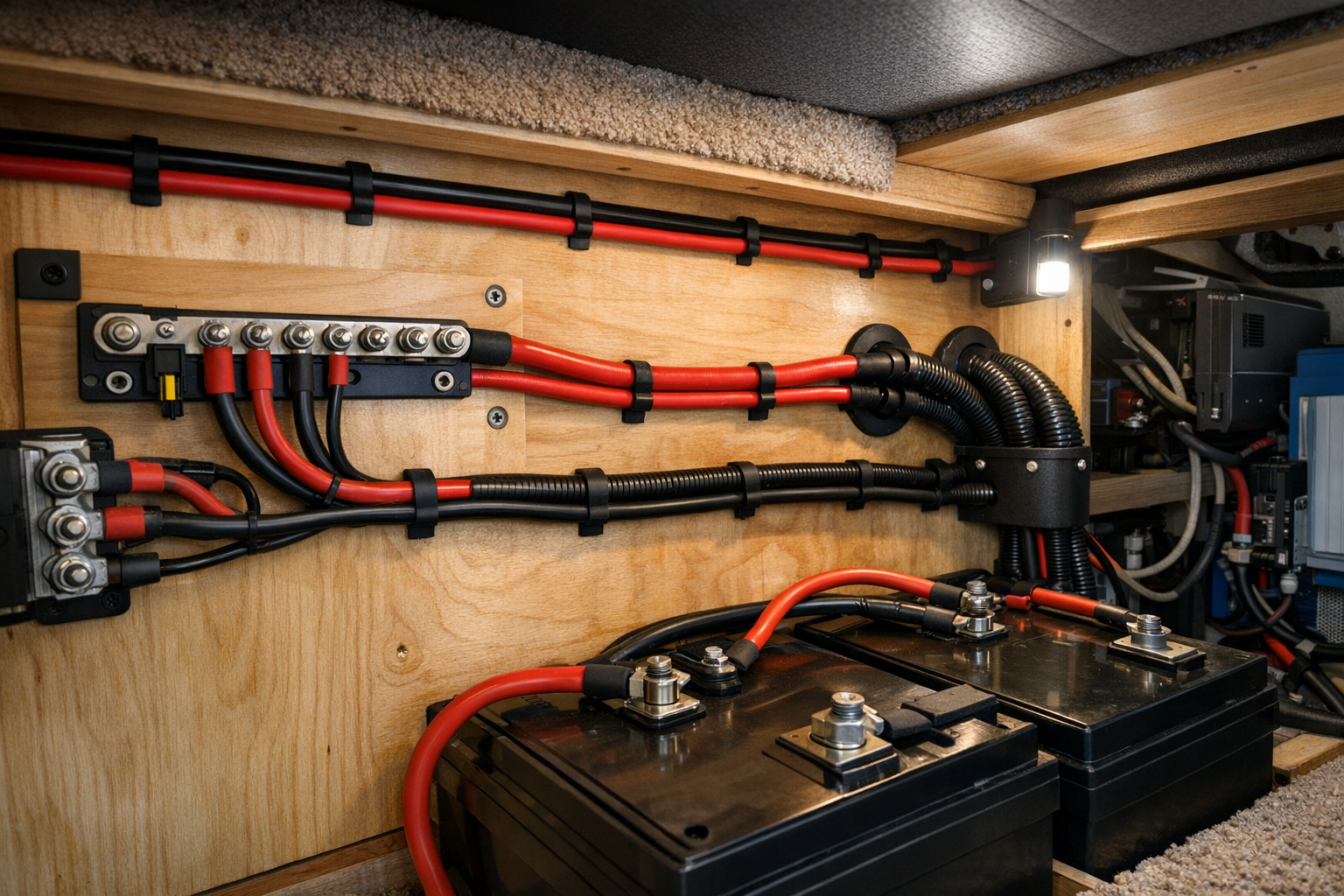
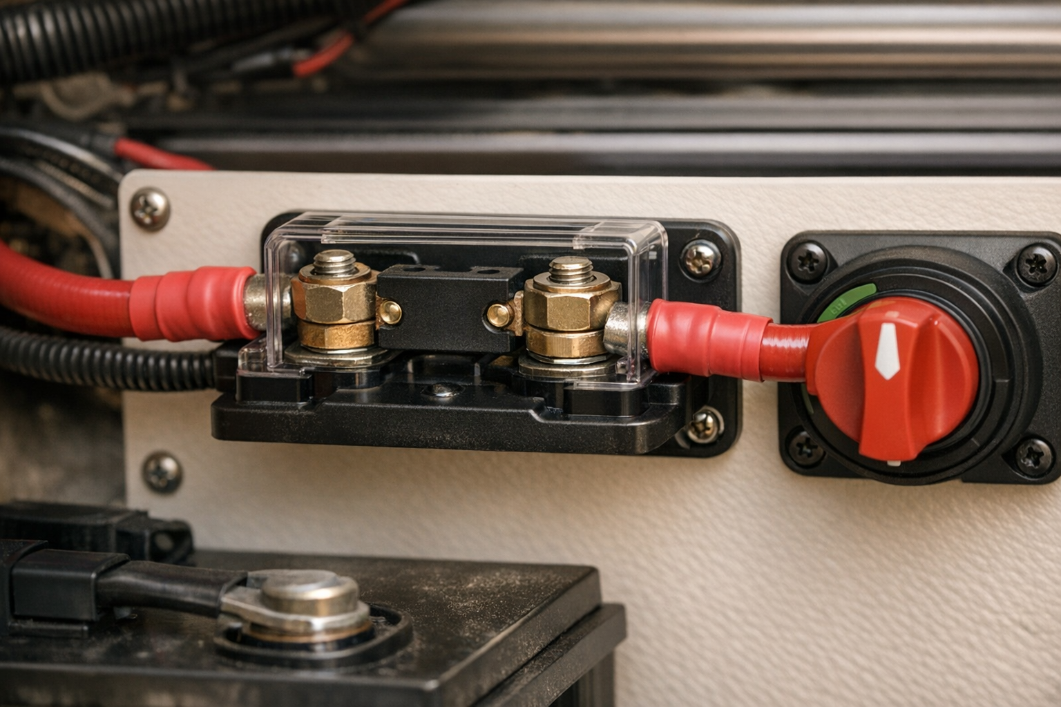
- Battery disconnect: Install a high-current battery disconnect switch between the battery bank and the main distribution point. This allows you to de-energize the entire DC system for maintenance. Ensure the switch is rated for the maximum current it will carry (including surge).
- Grounding: Bond all equipment grounding conductors to a single grounding bus bar. In an RV, the chassis typically serves as the ground reference. The inverter’s AC output neutral and ground should be bonded only at the inverter (if it’s the sole AC source) or at the transfer switch—never in both places, or you create a ground loop.
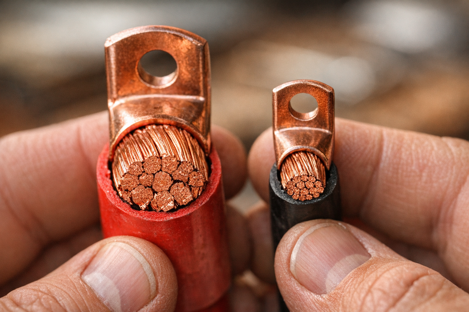
- Wire termination: Use hydraulically crimped lugs on all battery and inverter connections. Soldered connections are prohibited in most marine and RV standards because they can flow under heat and vibration, creating high-resistance joints. Apply adhesive-lined heat shrink over every lug crimp.
- Torque specs: Inverter and battery terminal bolts have specific torque values (often 6–10 Nm for M8 studs). Under-torqued connections create resistance, heat, and eventual failure. Use a torque wrench.
- Conduit and chafe protection: Any cable passing through a bulkhead, floor, or chassis member must be protected with a grommet or conduit fitting. Vibration in a moving RV will eventually saw through insulation against a raw metal edge.
Introduction
This guide walks through roof layout, mounting, wiring to a charge controller, and basic validation with a multimeter.
Step-by-Step Installation
Follow the steps in order: layout → mounting → cable entry → controller → battery → panels → test.
Recommended Gear
- Victron SmartSolar MPPT 100/30 — View on Amazon
- Renogy 100W Monocrystalline Panel — View on Amazon
- Battle Born 100Ah LiFePO4 Battery — View on Amazon
FAQs
- How Do Inverter Surges Affect Cable Size?
Surge current (typically 2× continuous rating) doesn’t usually dictate cable gauge directly, because surges last only a few seconds and copper has significant thermal mass. However, you must verify that the voltage drop at surge current, combined with battery sag, doesn’t push voltage below the inverter’s low-voltage disconnect threshold. On a 12 V system, this is often the binding constraint rather than ampacity. If your surge-current voltage drop exceeds 0.5 V, go up a gauge or shorten the run.
- Do I Need Separate Fusing for Each Cable Segment?
Yes. Each segment has a different current profile, a different cable gauge, and a different power source that could feed a fault
As an Amazon Associate, we earn from qualifying purchases. This helps keep SunAmpRV running.