RV Solar Panels: Series vs Parallel Wiring Guide
On this page

For most RV roofs with an MPPT charge controller, wire the panels in series. The higher voltage carries the same power on less current, so the cable down to the controller wastes less of it. Choose parallel when your panels get shaded at different times, by an air conditioner shroud, a roof vent or a tree, or when 12V-class panels charge a 12V battery through a PWM controller. With four or more panels, series-parallel combines the two. Four things decide which layout suits your rig: the controller’s voltage and current limits, the shade pattern on your roof, the panels’ own ratings and the length of the cable run.
TL;DR
- Default choice: series, for an MPPT controller, an open roof and a long cable run.
- Choose parallel: when panels are shaded at different times, or when a PWM controller charges a 12V battery from 12V-class panels.
- Four or more panels: series-parallel, such as 2S2P, balances voltage, current and the controller’s limits.
- Same watts either way: series adds the voltages, parallel adds the currents, and the array’s rated power doesn’t change.
- Check the controller: the array’s cold open-circuit voltage must stay under its PV voltage limit, and the short-circuit current under its PV current limit.
How Series, Parallel and Series-Parallel Work
The three layouts differ only in how the panel leads meet.
Series
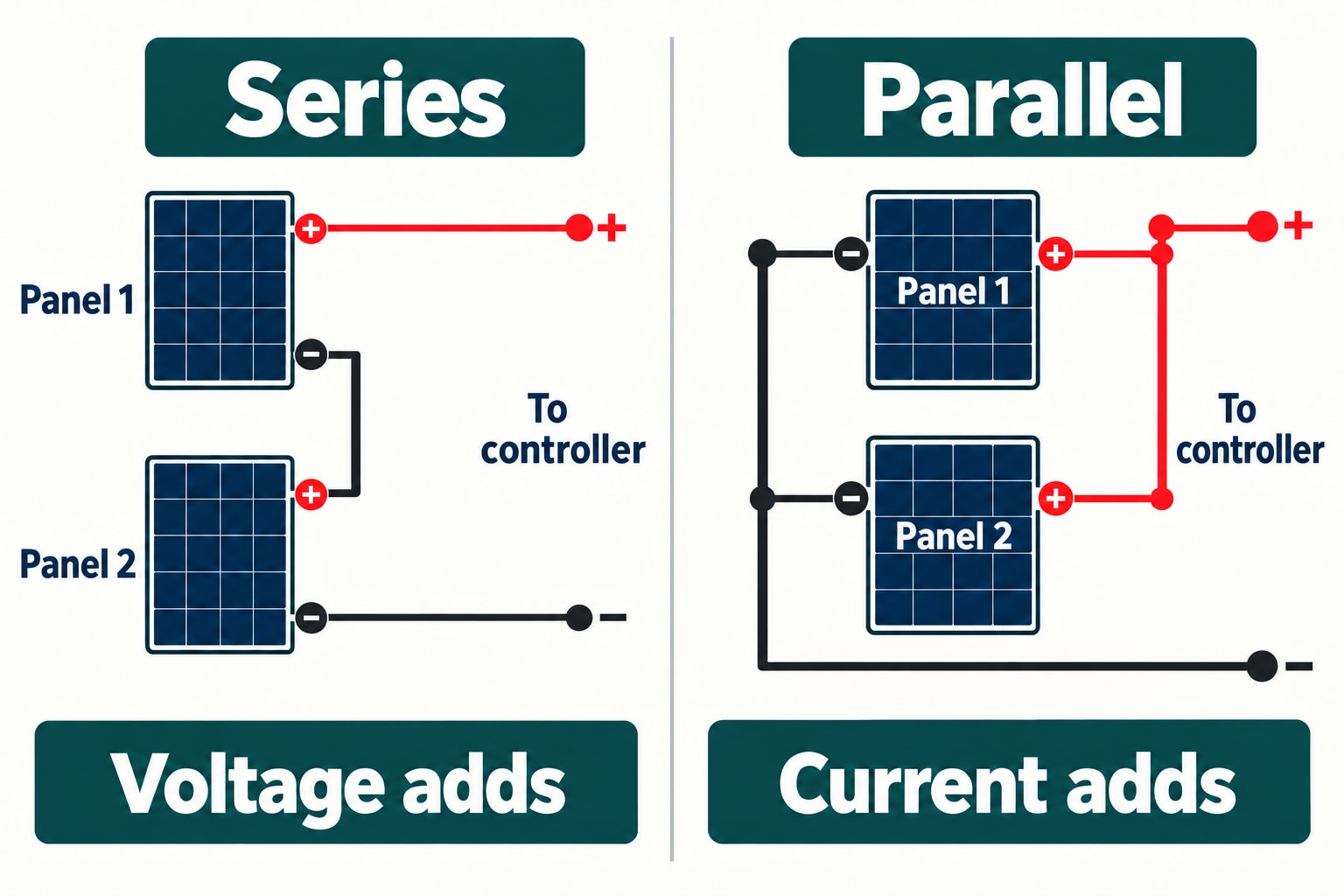
Connect the positive lead of one panel to the negative lead of the next, then run the two free leads to the controller. The voltages add up, while the current stays at that of a single panel, as long as the panels match.
Panel 1 (−) → Panel 2 (+)
Panel 2 (−) → controller PV (−)
Parallel
Join all the positive leads together and all the negative leads together, with branch connectors or a combiner box, and run one positive and one negative cable to the controller. The currents add up, and the voltage stays the same as one panel’s.
Panel 1 (−) and Panel 2 (−) → controller PV (−)
Series-Parallel
Build two or more identical series strings, then connect the strings in parallel. The shorthand counts both: 2S2P means two panels in series in each string and two strings in parallel, four panels in all. Within each string the voltages add, and across the strings the currents add.
String B: Panel 3 and Panel 4 in series
String A (+) and String B (+) → controller PV (+)
String A (−) and String B (−) → controller PV (−)
None of this changes your battery voltage. Wiring panels in series doesn’t turn a 12V RV system into a 24V one: an MPPT controller converts the array’s higher voltage down to the battery’s charging voltage and delivers correspondingly more current.
A 400 W Example
Take four identical 100 W panels with round example ratings: a maximum-power point of 20 V and 5 A, an open-circuit voltage of 24 V and a short-circuit current of 5.5 A, all at standard test conditions. They’re illustration values, not the specifications of a particular product. Here’s what the three layouts make of them:
Scroll sideways to see every column.
| Layout | Vmp | Imp | Rated Power | Voc | Isc |
|---|---|---|---|---|---|
| Four in parallel (4P) | 20 V | 20 A | 400 W | 24 V | 22 A |
| Four in series (4S) | 80 V | 5 A | 400 W | 96 V | 5.5 A |
| Two strings of two (2S2P) | 40 V | 10 A | 400 W | 48 V | 11 A |
Every layout is still a 400 W array. The wiring changes the mix of voltage and current, not the power. The four ratings do different jobs: Vmp and Imp describe the operating point in full sun; Voc is the voltage the array makes when nothing draws from it, which is what you check against the controller’s voltage limit; and Isc is the rated short-circuit current, used to check the controller’s PV input limit and to size the protection.
Check the Charge Controller
The controller decides which layouts are possible at all. A PWM controller is essentially a switch between the panels and the battery, so it pulls the array’s voltage down to near the battery’s. Extra voltage from series wiring is simply lost, so a PWM controller on a 12V battery calls for 12V-class panels in parallel. An MPPT controller decouples the two sides: it runs the array at its best voltage and converts the power down to the battery’s charging voltage, which is what makes series wiring pay off.
For an MPPT controller, check four limits. Victron’s SmartSolar MPPT 100/30 shows what they look like:
- Maximum PV voltage: 100 V, which the array’s open-circuit voltage on the coldest morning must stay below.
- Maximum PV short-circuit current: 35 A.
- Charge current: 30 A. That’s what it delivers to the battery, not a limit of 30 A from the panels.
- Voltage margin over the battery: it needs the PV voltage 5 V above the battery’s to start charging, and 1 V above it to carry on.
Victron’s nominal PV power for the 100/30 on a 12V battery is 440 W, so the 400 W example fits, and even the 4P layout’s 22 A short-circuit current stays under its 35 A input limit. At the battery, the controller turns the 2S2P array’s 40 V and 10 A into roughly 28 A at a 14.4 V charging voltage, minus conversion losses. The remaining question is voltage, and that’s where the weather comes in. When you choose a controller, our guide to sizing a charge controller covers the amp rating, and our MPPT charge controller guide covers what else to look for.
Why Cold Weather Can Change the Answer
A panel’s voltage rises as its cells get colder. With a Voc temperature coefficient of -0.30 percent per °C, an example value, and a cold morning of 14°F (-10°C), the open-circuit voltage climbs 10.5 percent above its 77°F (25°C) rating:
- 4S: 96 V × 1.105 = 106.1 V, above the 100/30’s 100 V limit.
- 2S2P: 48 V × 1.105 = 53.0 V, well inside it.
- 4P: 24 V × 1.105 = 26.5 V.
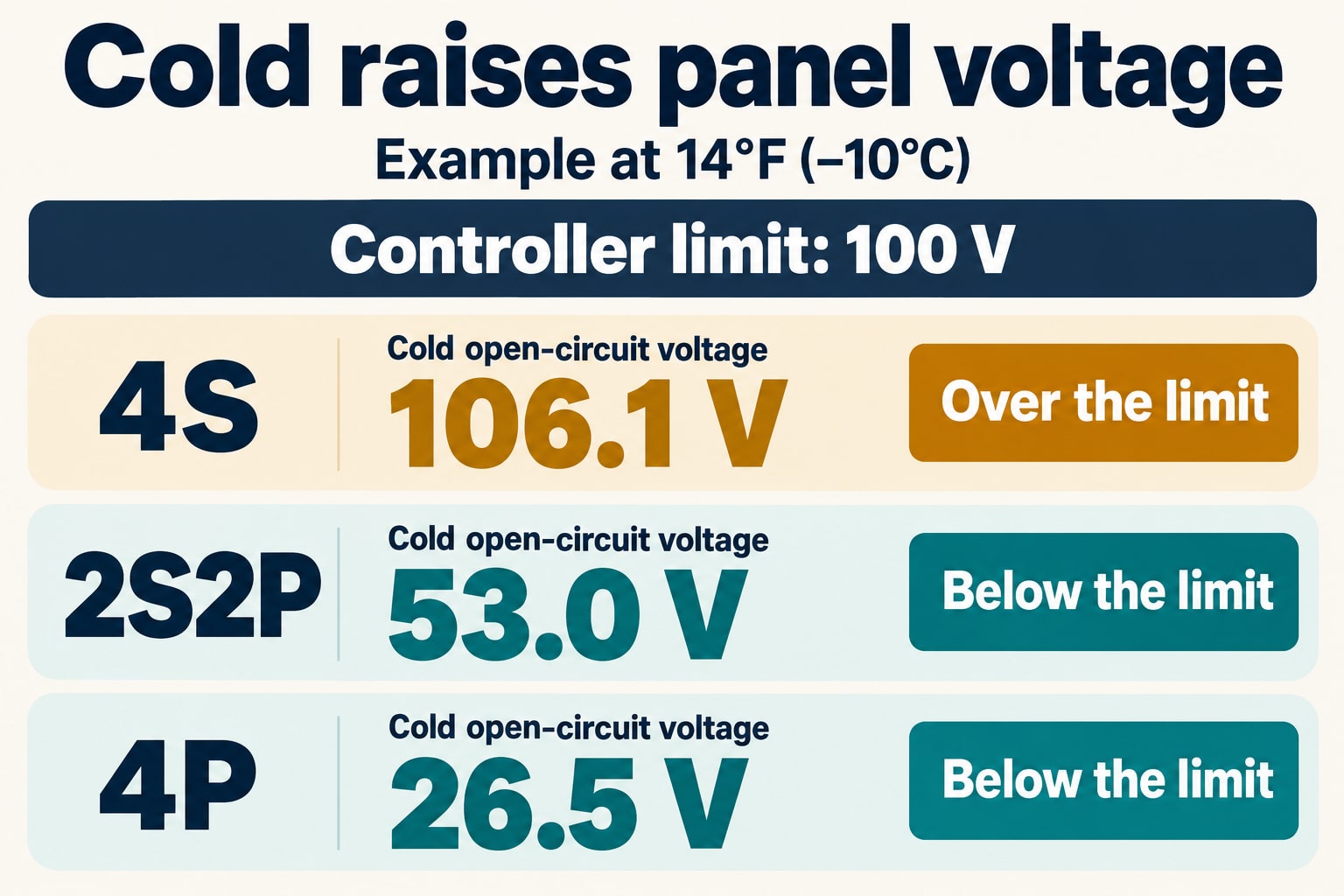
Four in series is ruled out for the 100/30, even though 96 V looks fine on paper. Both 4P and 2S2P meet its voltage and current limits in this example, but 2S2P cuts cable losses and leaves more voltage headroom when the panels get hot. The 4S string’s 106.1 V would fit a 150 V input limit, provided the controller’s other ratings also suit the array. For a real array, take the temperature coefficient from your own panels’ datasheet and plan for the lowest temperature you’re likely to camp in. The controller’s power limiting won’t save it from excess input voltage; only staying under the limit does.
Heat pushes the other way. Hot panels lose voltage, so on a summer roof the 4P array’s 20 V operating point sits much closer to a 14.4 V charging battery than the 2S2P array’s 40 V does, and the controller needs a margin above the battery to keep charging.
Shade, Clouds and Mixed Panels
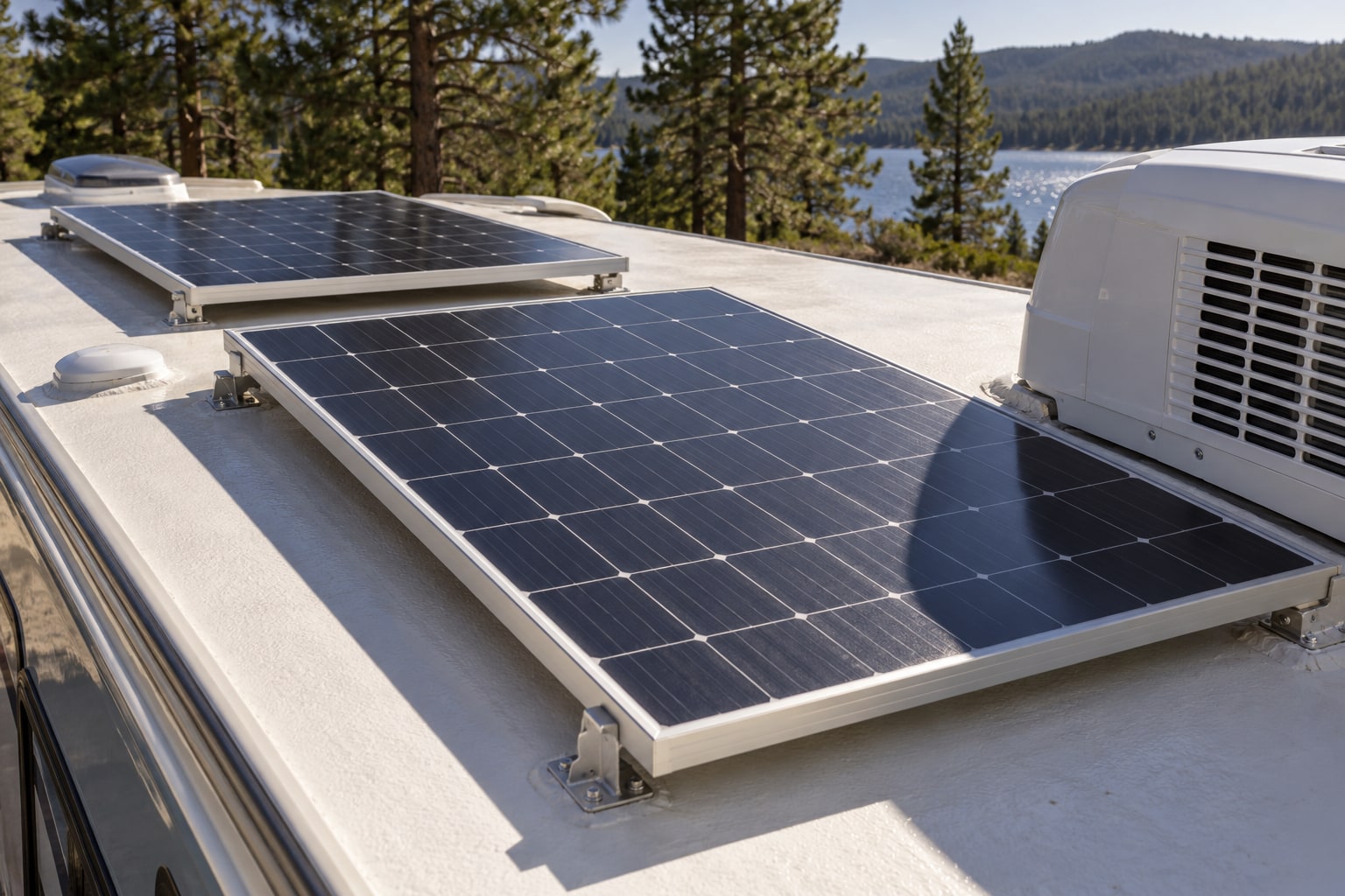
Shade is the main reason to choose parallel. Bypass diodes route current around shaded cell groups, so one shadow doesn’t automatically shut down the whole string. Bypassing cells reduces the string’s voltage, which still has to stay high enough for the controller to charge. In parallel, each panel delivers what it can at the shared voltage, so a shadow that crosses one panel at a time, from the AC unit, a vent or a tree beside the campsite, often costs less. It isn’t a guarantee, though: a heavily shaded panel can drop out of a parallel array too.
Clouds are a different case. An overcast sky mostly cuts the current from every panel at once, so it doesn’t favor either layout.
Mixed panels need care in both layouts. The simplest array uses one panel model throughout, which is also what Victron recommends. If you mix, match Imp for panels in series and Vmp for panels in parallel. A series string shares one current, while parallel panels share one operating voltage, so mismatched panels can’t all run at their own best operating point. Two panels with the same watt rating can still be a poor match. Panels with very different ratings, or on different parts of the roof, often work best on separate controllers.
Cable Losses: Why Higher Voltage Helps
Series wiring’s big practical advantage is the cable. At a fixed wattage, twice the voltage means half the current, and cable loss falls to a quarter. The voltage drop on the run from the roof to the controller is:
Run the 400 W example through a 15-foot route from the roof to the controller, 30 feet of 10 AWG conductor counting both wires, at an assumed 0.999 Ω per 1,000 feet, a typical room-temperature figure for copper:
Scroll sideways to see every column.
| Layout | Current in the Cable | Voltage Drop | Share of Array Voltage | Power Lost |
|---|---|---|---|---|
| 4P at 20 V | 20 A | 0.60 V | 3.0% | 12 W |
| 2S2P at 40 V | 10 A | 0.30 V | 0.75% | 3 W |
| 4S at 80 V | 5 A | 0.15 V | 0.19% | 0.75 W |
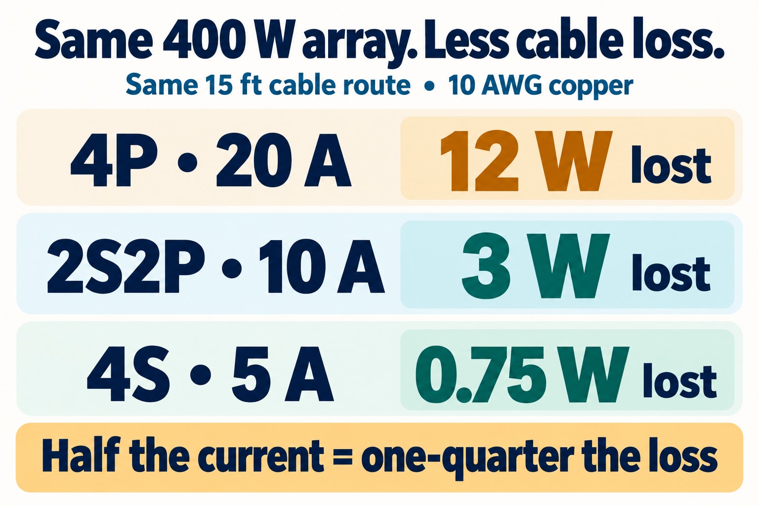
Moving from 4P to 2S2P cuts the loss in this cable to a quarter, from 12 W to 3 W. That’s 9 W saved in full sun, not four times the charging: the array still has the same 400 W rating. Voltage drop and the cable’s current rating are separate checks, too. A small drop doesn’t prove a cable can carry the current safely, so check its ampacity after allowing for roof heat and bundled cables, and remember that a hot cable also has slightly more resistance than the room-temperature figure.
Fuses for Parallel Strings
Fuses on the panel side guard against a fault drawing current backward through a panel or cable. When strings run in parallel, a short in one string lets the others push their current into it. Size the panel side from the short-circuit current, not from a clamp-meter reading at noon:
- Fuse size: Renogy’s fuse guide multiplies a string’s Isc by 1.56 and rounds up. For the example panels, 5.5 A × 1.56 = 8.6 A, so a 10 A fuse, provided the panel’s label allows a series fuse of at least 10 A. The fuse must never exceed the label’s maximum. Use fuses and holders intended for PV circuits, with a DC voltage rating above the string’s cold-weather Voc.
- How many strings: with two parallel strings, check the panel manual before leaving out string fuses: some makers allow it when reverse current stays within the permitted limits, while others require a fuse in every string. With three or more strings, plan on individual string fuses.
- Cables and connectors: the fuse protects them too, so check their current ratings against it.
- The battery side: the fuse between controller and battery is a separate decision, sized for the controller’s output and mounted close to the battery. For both sides, see our RV fuse and breaker guide.
If a fuse keeps blowing, find the cause first. A bigger fuse removes the protection, not the fault.
Connecting the Panels Safely
- Check polarity first. Measure each string’s open-circuit voltage before it goes anywhere near the controller. Expect a positive reading near the Voc you planned.
- Use a proper DC disconnect. Choose a breaker or isolator that can interrupt DC under load, rated for the array’s current and above its cold-weather Voc, so the panels can be switched off safely.
- Match the connectors. Mate connectors only with the same brand and type; according to Stäubli, mixed brands can raise contact resistance. Connectors that fit together aren’t proof that they belong together.
- Don’t unplug under load. Open the PV disconnect before changing the wiring. Parallel strings can still feed one another with the controller disconnected, so isolate them with suitable DC switches or cover all connected panels with opaque material. Make sure no current is flowing before you separate a connector.
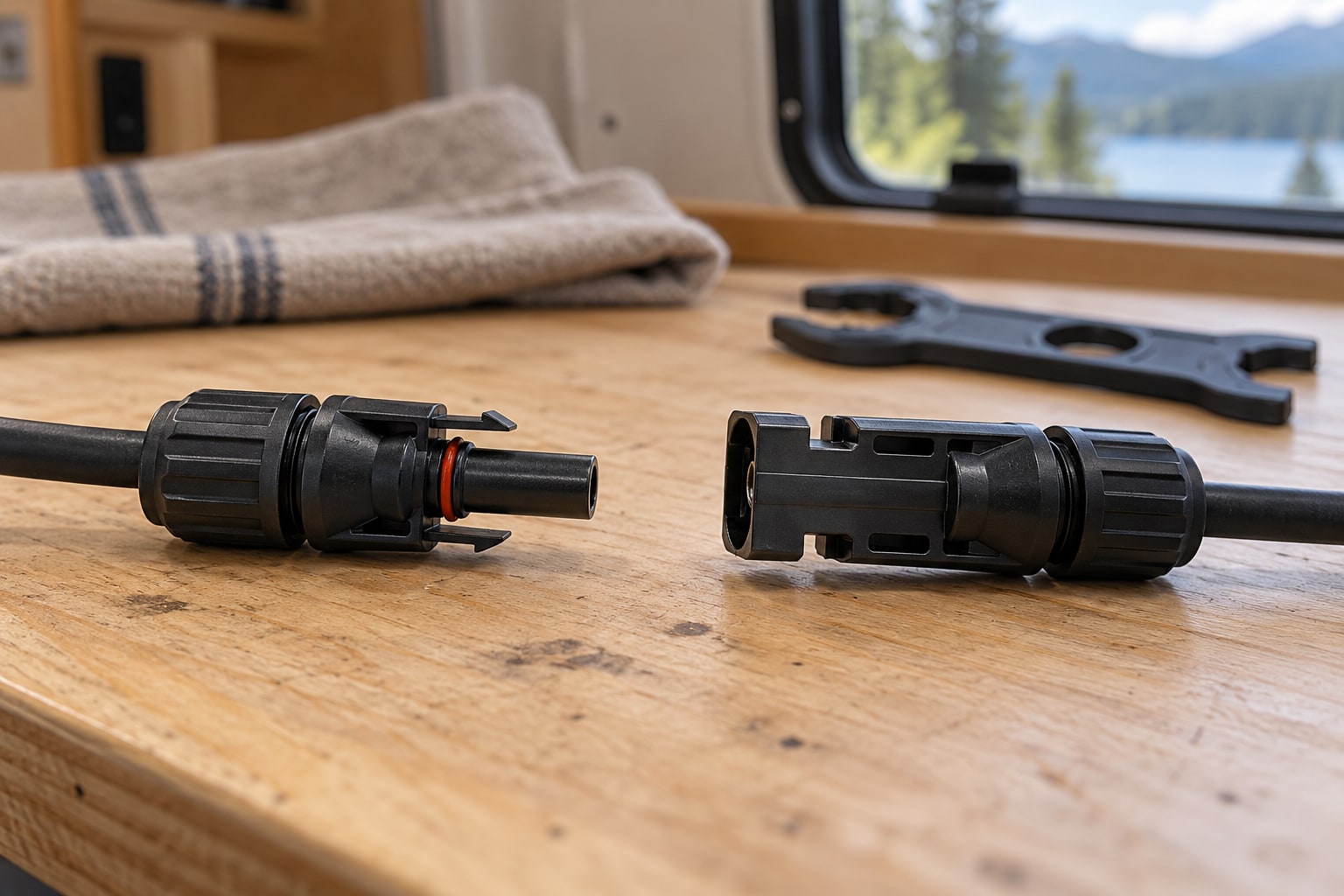
Inspect matching connector halves while isolated. Their shape alone does not prove compatibility: use the same maker and type, and never separate them while current is flowing. - Follow the controller’s order. Most MPPT controllers want the battery connected before the panels, and the panels switched off first when you shut down.
- Measure cable loss at both ends. A gap between the panel’s open-circuit voltage and the controller’s reading under load says nothing about the cable, because Voc is always higher than the operating voltage. Measure at both ends of the run at the same moment, while the array is charging.
Our step-by-step guide to installing RV solar panels covers mounting and cable routing. If a finished system won’t charge, work through our troubleshooting guide for RV solar.
FAQs
- Is series or parallel better when part of the roof is shaded? Parallel usually copes better when the shade falls on one panel at a time, such as the air conditioner’s afternoon shadow, because each panel adds its own output at the common voltage. Bypass diodes let a shaded series string keep producing at a lower voltage, but only while that voltage stays above what the controller needs to charge. If one panel sits in shade for much of the day, giving it its own controller can beat either layout.
- Can I wire panels in series on a 12V battery? Yes, with an MPPT controller, which converts the higher array voltage down to the 12V battery’s charging voltage. With a PWM controller, stay with 12V-class panels in parallel, because PWM pulls the array down to battery voltage and the extra voltage goes unused.
- Can I mix different solar panels? You can, but match the right rating: similar operating current for panels in series, similar operating voltage for panels in parallel. Equal watts alone don’t make two panels compatible, and very different panels usually do better on separate controllers.
- What does 2S2P mean? Two strings of two: each string has two panels in series, and the two strings are connected in parallel, for four panels. With the example panels, that gives 40 V and 10 A, and the cold-morning open-circuit voltage stays near 53 V, well inside a 100 V controller’s limit.
- Do I need fuses between the panels and the controller? It depends on the number of parallel strings. With two, the panel manual decides whether string fuses can be left out; with three or more, plan on one per string. Size them from the short-circuit current, never above the panel’s maximum series fuse rating, and fuse the controller-to-battery cable near the battery as well.
Conclusion
With an MPPT controller and an open roof, series or series-parallel is usually the better choice: the same power reaches the controller on less current, with less lost in the cable. Parallel earns its place when shade hits the panels unevenly, when a PWM controller pairs 12V-class panels with a 12V battery, or when a series string’s cold voltage would exceed the controller’s limit. In the 400 W example, 2S2P met a 100 V controller’s limits on a 14°F morning while cutting the cable loss to a quarter of the parallel layout’s. Check your own panels’ ratings, the controller’s limits and the coldest morning on your travels, and the numbers will point you to the right layout.
Spot an error or an outdated detail in this guide?
Report it