TL;DR
- Measure round-trip: Always count both outgoing and return conductors when calculating cable length.
- Target ≤3% drop: Use the voltage-drop formula and the AWG resistance table to select the right gauge.
- Protect every run: Fuse or breaker must be rated to the cable ampacity, not the load.
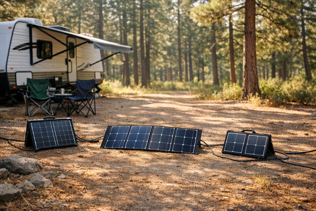
Introduction to RV solar cable sizing
A 25-foot panel-to-controller run carrying 30 A on 10 AWG copper drops roughly 1.53 V—over 12 percent of a 12 V nominal battery bank. That single cable choice can waste more energy than a cloudy afternoon. Correct cable sizing protects your investment and captures every available watt.
Why Cable Sizing Matters in RV Solar Systems
Every foot of copper conductor between your solar panels and your battery bank introduces electrical resistance. Resistance converts a portion of your solar harvest into heat rather than stored energy. In a fixed residential installation operating at 48 V, modest resistance is tolerable. In an RV running at 12 V nominal, the same absolute voltage loss represents a far larger percentage of the system voltage, making cable sizing a first-order design decision rather than an afterthought.
Undersized cables create three compounding problems:
- Reduced charging efficiency. The charge controller sees a lower input voltage and may throttle output or fail to reach absorb/float thresholds.
- Heat generation in confined spaces. Wall cavities, under-floor channels, and roof penetrations offer poor heat dissipation, raising fire risk.
- Accelerated terminal corrosion. Elevated temperatures at crimp points oxidize copper faster, degrading connections over time.
Oversized cables waste money and are harder to route through tight RV conduit paths. The goal is the smallest AWG that keeps voltage drop within an acceptable window—typically 3 percent or less on the DC side of the system.
Key Concepts Before You Start
Nominal Voltage vs. Actual Voltage
A “12 V” battery bank rests near 12.6–12.8 V when fully charged and can sag to 11.8 V under load. A “24 V” bank operates around 25.2–25.6 V at rest. When calculating percentage voltage drop, use the nominal value (12 V or 24 V) as the reference. This yields a slightly conservative result—exactly what you want for a mobile platform subject to vibration, temperature swings, and connector aging.
Round-Trip Length
Current must travel from the source to the load and back. A panel mounted 15 feet from the charge controller requires 30 feet of conductor in the circuit. Every voltage-drop calculation must account for this round-trip distance.
Forgetting to double the length is the single most common sizing mistake in DIY RV solar builds.
Usable Battery Capacity
No battery technology delivers the usable share of its rated capacity (varies by chemistry). Lithium iron phosphate (LiFePO4) banks are typically planned at 80–90 percent depth of discharge, while lead-acid banks should not be drawn below 50 percent. Cable sizing does not change these limits, but understanding them prevents you from oversizing panels and cables to chase capacity that chemistry will never release.
Step-by-Step Cable Sizing
- Determine total current (A). For the panel-to-controller run, divide total panel wattage by the panel voltage at maximum power (Vmp). Example: two 200 W panels wired in parallel at a Vmp of 18.5 V produce roughly 21.6 A. For the controller-to-battery run, divide total panel wattage by the battery nominal voltage: 400 W ÷ 12 V ≈ 33.3 A. Always use the higher current figure for each specific segment. If your MPPT controller documentation lists a maximum output current, use that value instead—see MPPT charge controllers for details on controller ratings.
- Measure the round-trip length (ft). Physically route a tape measure or a length of paracord along the exact path the cable will follow—over cabinets, through floor channels, around wheel wells. Add 10 percent for service loops and connector slack. Multiply the one-way distance by two. A 20-foot one-way path becomes a 40-foot round-trip conductor length; with the 10 percent margin, plan for 44 feet.
- Apply the voltage-drop formula. Plug your round-trip length, current, and the resistance per 1,000 feet for a candidate AWG into the formula below. Compare the result against your target percentage (≤ 3 percent of nominal system voltage).
- Select AWG from the resistance table. If the calculated drop exceeds 3 percent, move to the next larger (lower AWG number) conductor and recalculate. Repeat until the drop is acceptable. Then verify that the chosen AWG’s ampacity rating exceeds your maximum current with margin for the ambient temperature inside the RV.
- Size the fuse or breaker. Select an overcurrent protection device rated for the cable’s ampacity, not the expected operating current. The fuse protects the wire, not the appliance. Place fuses as close to the battery positive terminal as physically possible.
- Document everything. Record the AWG, run length, fuse size, and terminal torque specs on a laminated card mounted near the battery compartment. Future you—or the next owner—will appreciate it.
Voltage-Drop Formula
The factor of 2 accounts for the round-trip path of current—positive conductor out, negative conductor back. “Length” is the one-way distance in feet. “Resistance” is the DC resistance of the chosen copper conductor gauge at 20 °C (68 °F), expressed in ohms per 1,000 feet. Values appear in the AWG table below or on the conductor manufacturer’s data sheet.
To convert the absolute voltage drop into a percentage:
The widely accepted threshold for DC solar circuits is 3 percent. Some designers target 2 percent on long runs or critical feeds to the inverter—see RV inverter sizing for inverter input requirements. Staying at or below 3 percent ensures the charge controller can reliably reach absorption and float set points without the cable eating into voltage headroom.
Worked Examples
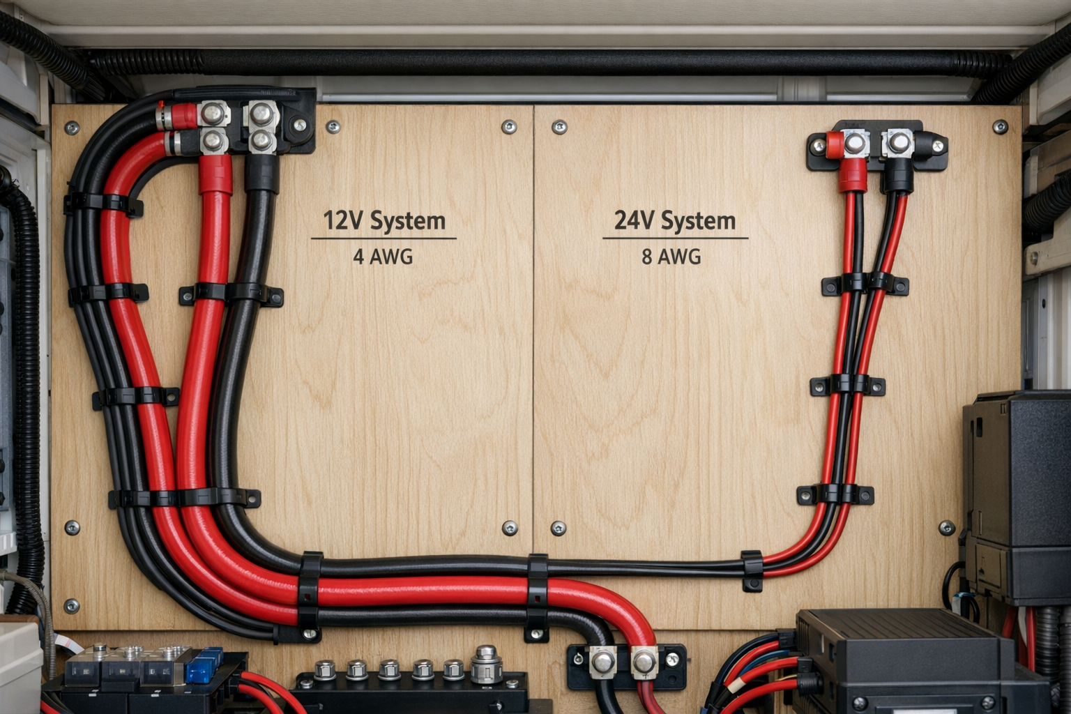
Example 1: 12 V System — Panel to Controller
Suppose you have 400 W of rooftop solar (two parallel panels, Vmp ≈ 18.5 V each) feeding an MPPT controller. The one-way cable run from the roof combiner box to the controller inside the RV is 18 feet.
Step 1 — Current: 400 W ÷ 18.5 V ≈ 21.6 A. Round up to 22 A for margin.
Step 2 — Round-trip length: 18 ft × 2 = 36 ft. Add 10 percent: 36 × 1.10 ≈ 40 ft (one-way = 20 ft for formula input).
Step 3 — Trial with 10 AWG copper (1.018 Ω/1000 ft):
Percentage of panel Vmp: (0.896 / 18.5) × 100 ≈ 4.84 %. That exceeds 3 percent.
Step 4 — Try 8 AWG copper (0.641 Ω/1000 ft):
Percentage: (0.564 / 18.5) × 100 ≈ 3.05 %. Borderline. In an RV that will sit in desert sun where cable temperatures climb well above 20 °C, stepping up to 6 AWG (0.403 Ω/1000 ft) drops only 0.355 V (1.92 %)—a comfortable choice.
Now consider the controller-to-battery segment. The MPPT controller converts the higher panel voltage down to battery voltage, so current increases. At 12 V nominal: 400 W ÷ 12 V ≈ 33.3 A. If the controller-to-battery run is only 4 feet one-way:
Percentage: (0.171 / 12) × 100 ≈ 1.42 %. An 8 AWG cable works fine for this short, high-current segment. If the run were longer—say 8 feet—the drop would double to about 2.85 %, nudging you toward 6 AWG.
Example 2: 24 V System — Panel to Controller
A larger Class A motorhome runs a 24 V battery bank with 800 W of rooftop solar (four panels configured as two series strings of two, Vmp per string ≈ 37 V). The one-way run from the roof junction box to the controller is 30 feet.
Step 1 — Current: Each series string produces 800 W ÷ 2 strings = 400 W at 37 V, so 400 W ÷ 37 V ≈ 10.8 A per string. The two strings are paralleled at the combiner, yielding 21.6 A total to the controller. Use 22 A.
Step 2 — Round-trip length: 30 ft × 2 = 60 ft. With 10 percent margin: 66 ft (one-way for formula = 33 ft).
Step 3 — Trial with 10 AWG copper (1.018 Ω/1000 ft):
Percentage of Vmp: (1.478 / 37) × 100 ≈ 4.00 %. Still over 3 percent.
Step 4 — Try 8 AWG copper (0.641 Ω/1000 ft):
Percentage: (0.931 / 37) × 100 ≈ 2.52 %. Under 3 percent—acceptable.
For the controller-to-battery segment at 24 V: 800 W ÷ 24 V ≈ 33.3 A. With a 6-foot one-way run on 8 AWG:
Percentage: (0.256 / 24) × 100 ≈ 1.07 %. The 24 V system’s higher voltage inherently halves the percentage drop compared to 12 V for the same wattage and cable—one of the strongest arguments for upgrading to a 24 V bank in larger RVs.
AWG to mm² and Resistance Table
The table below lists DC resistance values for solid, uncoated copper conductors at 20 °C (68 °F). Stranded conductors of the same AWG have slightly higher resistance (typically 1–2 percent more) due to air gaps and lay length, but the difference is within the rounding shown here. Always confirm with the cable manufacturer’s data sheet.
| AWG | Approximate mm² | Resistance (Ω/1000 ft) | Resistance (Ω/km) | Typical RV Application |
|---|---|---|---|---|
| 14 | 2.08 | 2.525 | 8.284 | Branch circuits, small loads |
| 12 | 3.31 | 1.588 | 5.211 | Panel-to-combiner jumpers |
| 10 | 5.26 | 1.018 | 3.340 | Short panel runs, small systems |
| 8 | 8.37 | 0.641 | 2.103 | Panel-to-controller, moderate runs |
| 6 | 13.30 | 0.403 | 1.322 | Controller-to-battery, longer panel runs |
| 4 | 21.15 | 0.253 | 0.830 | High-current battery feeds, inverter cables |
| 2 | 33.62 | 0.159 | 0.522 | Large inverter feeds, bus bars |
| 1/0 (0) | 53.49 | 0.100 | 0.328 | High-power inverter runs, chassis grounds |
Important: Keep total voltage drop at or below 3 percent on every DC segment of your solar system. On runs that feed sensitive electronics or inverters with narrow input windows, target 2 percent for additional headroom. Resistance increases roughly 0.4 percent per degree Celsius above 20 °C, so cables routed through engine bays or sun-baked roof raceways should be sized one step larger than the bare calculation suggests.
Understanding Ampacity vs. Voltage Drop
Ampacity and voltage drop are two separate constraints, and your cable must satisfy both.
Ampacity is the maximum current a conductor can carry continuously without exceeding its insulation temperature rating. The National Electrical Code (NEC) Table 310.16 and ABYC standards publish ampacity values for various insulation types and ambient temperatures. Voltage drop, on the other hand, is a performance metric—how much energy you lose in transit.
In most RV solar installations, voltage drop is the binding constraint. A 10 AWG THWN-2 conductor is rated for 35 A at 30 °C in free air, which easily handles a 22 A solar feed. But as Example 1 showed, 10 AWG may drop too much voltage on a 20-foot run at that current. You end up choosing 6 or 8 AWG not because 10 AWG would melt, but because 10 AWG wastes too many watts.
The exception is very short, very high-current runs—like a 2-foot cable from a 3,000 W inverter to a 12 V battery bank pulling 275 A at full load. There, ampacity dominates, and you may need 2/0 or 4/0 cable even though the voltage drop on 2 feet is trivial. See RV inverter sizing for inverter cable requirements.
Installation Tips
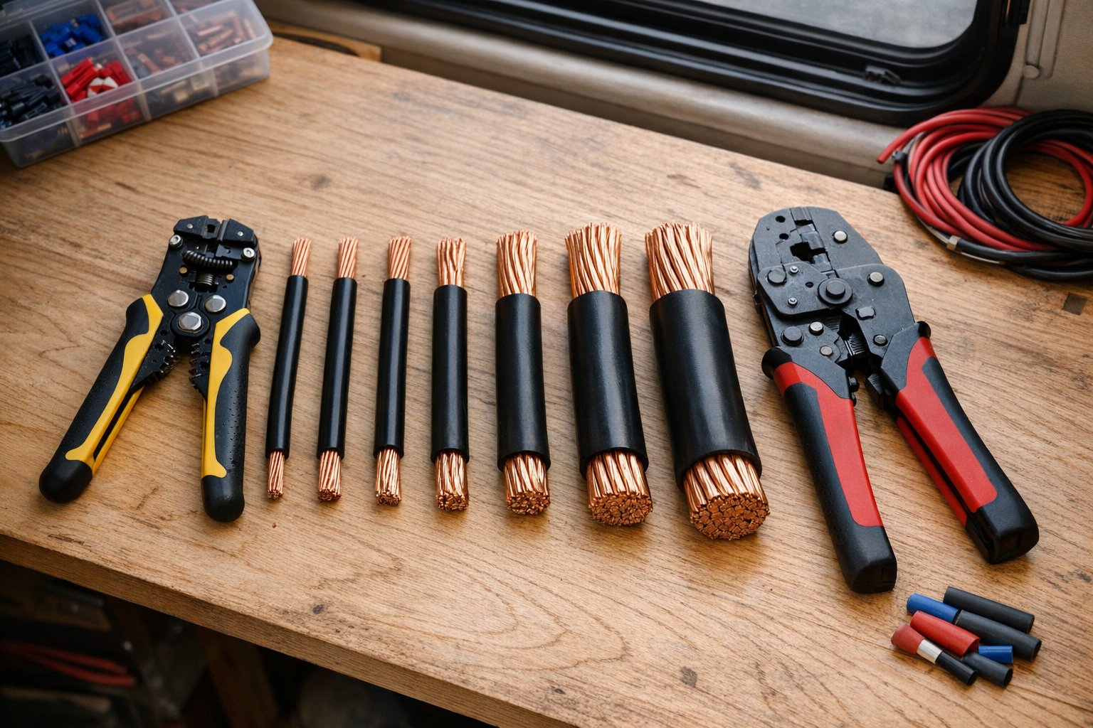
- Use tinned marine-grade copper wire. RVs are exposed to humidity, road salt spray, and condensation. Tinned stranded copper resists corrosion far better than bare copper. The slight cost premium pays for itself in longevity.
- Crimp, don’t solder, for power connections. Solder joints become brittle under vibration and can wick up the conductor, creating a stress riser where the stiff soldered section meets flexible stranded wire. Use adhesive-lined heat-shrink crimp connectors or hydraulic crimp lugs for cables 8 AWG and larger.
- Support cables every 18 inches. Unsupported cable runs bounce and chafe against sharp edges. Use cushioned clamps (Adel clamps) or cable trays. Avoid zip ties on sharp metal—they cut through insulation over time.
- Separate positive and negative conductors where possible. Running them in the same loom is acceptable for most low-voltage DC work, but keeping them on opposite sides of a conduit or channel reduces short-circuit risk if one conductor’s insulation is damaged.
- Seal every roof penetration. Use a weatherproof cable entry gland (often called a “solar cable entry plate”) with self-leveling sealant rated for EPDM or TPO roofing. A leaking roof penetration will cause more damage than an undersized cable ever will.
- Torque battery terminals to spec. Loose battery connections are the number-one cause of DC fires in RVs. Lithium battery manufacturers typically specify 70–100 in-lb for M8 terminal bolts. Use a torque wrench, not a guess.
- Leave service loops. At both the roof junction box and the charge controller, leave 12–18 inches of extra cable coiled neatly. This allows future re-termination if a crimp fails or if you relocate equipment.
- Color-code consistently. Red for positive, black (or blue in some European standards) for negative. If you must use the same color for both, mark the negative conductor with white tape every 12 inches.
Safety & Common Mistakes
- Size fuses and breakers to the cable ampacity, not the load — undersized protection cannot prevent overheating.
- Always measure round-trip length; ignoring the return conductor undersizes the cable.
- Derate ampacity for bundled runs and high-ambient temperatures.
- Use properly crimped and heat-shrunk terminals — loose connections create hot spots.
- Route cables away from heat sources and sharp edges; secure every 18 in (45 cm).
FAQs
- What voltage-drop percentage should I target? Keep total drop at or below 3 percent on each DC segment (panel-to-controller and controller-to-battery independently). For inverter feed cables or runs longer than 30 feet, targeting 2 percent provides a practical safety margin against temperature-induced resistance increases and connector aging.
- Does stranded wire have different resistance than solid wire of the same AWG? Yes, but the difference is small—typically 1 to 2 percent higher for stranded due to the helical lay of individual strands and tiny air gaps. For RV solar sizing, the published AWG resistance values are close enough. Always use stranded wire in RVs; solid wire fatigues and breaks under road vibration.
- Can I run solar cables through the same conduit as 120 V AC wiring? NEC Article 690.31 generally prohibits mixing PV source circuits with conductors of other systems in the same raceway unless all conductors are rated for the highest voltage present. In practice, keep DC solar cables in their own dedicated conduit or cable chase to simplify maintenance and comply with inspection requirements.
- How do I size cable for panels wired in series versus parallel? Series wiring increases voltage while keeping current the same as a single panel. Parallel wiring keeps voltage the same but adds the currents of each panel together. Higher current demands thicker cable. Two 200 W panels in series at 10.8 A need thinner cable than the same panels in parallel at 21.6 A—but the series configuration requires a controller with a higher voltage input rating.
- Should I use welding cable for battery-to-inverter runs? Welding cable (SGR or SGT rated) is highly flexible and handles high current well, making it popular for short inverter feeds. However, its insulation is rated for intermittent duty in welding applications, not continuous DC loads. For permanent RV installations, UL-listed battery cable or marine-grade cable with XLPE or EPR insulation is the safer, code-compliant choice.
Conclusion
Correct RV solar cable sizing comes down to four decisions made in sequence. First, measure the actual one-way cable path and double it to get the round-trip conductor length—add 10 percent for routing slack. Second, calculate the maximum current on each segment separately: use panel Vmp for the roof run and battery nominal voltage for the controller-to-battery run, remembering that MPPT conversion raises current on the battery side. Third, apply the voltage-drop formula with the copper resistance value for your candidate AWG and confirm the result stays at or below 3 percent of the segment’s reference voltage; if it doesn’t, step up one gauge and recalculate. Fourth, install a DC-rated fuse or breaker on every positive conductor, sized to the cable’s ampacity and placed within inches of the battery terminal.
For a typical 400 W, 12 V system with a 20-foot roof run, 6 AWG tinned copper from panels to controller and 8 AWG from controller to battery—protected by a 30 A string fuse and a 50 A battery fuse respectively—delivers under 2 percent drop on each segment and keeps the installation safe, efficient, and ready for years of travel.