RV Fuse & Breaker Sizing: a Complete Install Guide
On this page
TL;DR: Quick Summary
- Fuse for the wire, not the load: Rate protection above the circuit’s continuous current and at or below the wire’s ampacity — never resolve a conflict with a bigger fuse.
- Match the fuse family to the location: Class T on lithium main cables, MRBF at battery terminals, ANL on busbar feeds, blade fuses for branch circuits.
- Protect at the source, then verify: Mount each fuse within inches of where the conductor gets power, energize progressively, and check for millivolt drops under load.
Introduction
A fuse or circuit breaker in an RV has exactly one primary job: to protect the wire it is connected to, not the appliance at the end of it. If the overcurrent device is rated higher than the wire’s ampacity, a short circuit can heat the copper past the insulation’s failure point before the fuse ever blows — and in a vehicle built largely of wood, foam, and plastic, that is how electrical fires start. The core sizing rule is simple to state and easy to get wrong: the fuse or breaker must be rated above the circuit’s maximum continuous current (usually with an equipment-specific sizing margin) and below the ampacity of the wire it protects. Every correct decision in this project flows from that single sentence.
DC circuits make this discipline especially important. At 12V, currents are large — a modest load in watts becomes a substantial load in amps — and battery banks, particularly lithium banks, can dump enormous short-circuit current into a fault. That is why the type of fuse (ANL, MRBF, Class T, blade-style ATO/ATC) matters just as much as the amp rating printed on it.
What You’ll Need
Gather documentation before hardware. Sizing decisions come from datasheets and measurements, not guesses, so the paperwork is as important as the tools.
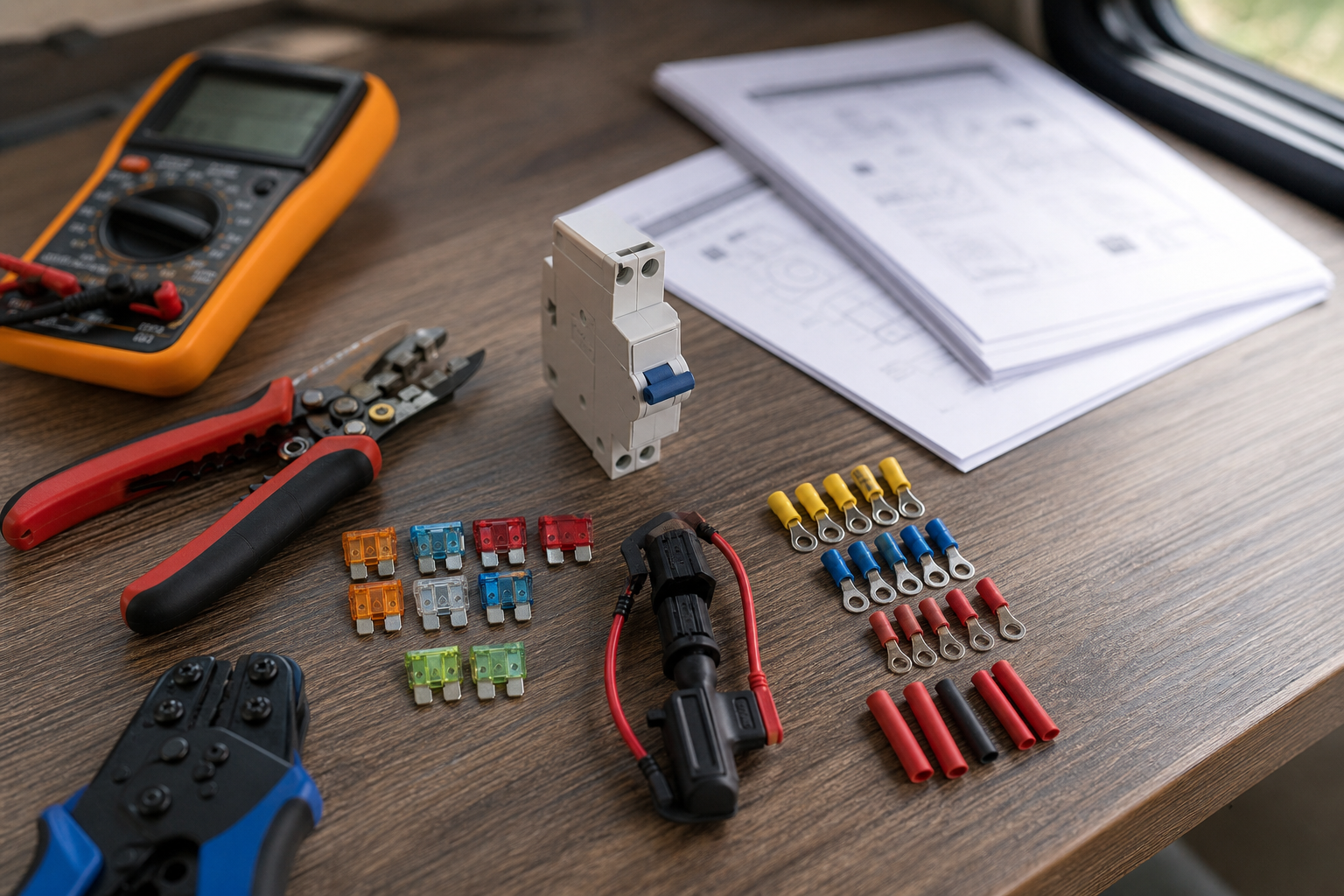
- ☐ Manufacturer datasheets or nameplate data for every load and charge source (inverter, charge controller, DC-DC charger, pumps, fans, refrigerator, lighting circuits)
- ☐ A wiring diagram of your system, even a hand-drawn one, showing every conductor, its gauge, and its length
- ☐ Digital multimeter (DC volts, continuity) — essential for testing
- ☐ DC clamp meter — the most reliable way to measure real current draw on loads without a clear datasheet
- ☐ Wire ampacity reference for your specific wire type and insulation temperature rating (the wire manufacturer’s published table)
- ☐ Fuse holders or breaker mounts appropriate to each fuse type (ANL holder, MRBF terminal mount, Class T holder with cover, blade-fuse block)
- ☐ Correctly rated fuses/breakers determined by the sizing steps below — buy after calculating, not before
- ☐ Insulated tools and a torque wrench or torque screwdriver with the driver bits for your terminal hardware
- ☐ Heat-shrink lugs, a proper crimper for the cable sizes in your system, and cable-cutting tools
- ☐ Dielectric grease or terminal protectant for exposed studs
- ☐ Labels or a label maker for marking every protected circuit
- ☐ Insulating gloves and safety glasses
Preparation checklist — complete before touching any wiring:
- ☐ Every circuit is listed in a worksheet with its wire gauge, wire length, and load identified
- ☐ You know your battery chemistry and its short-circuit current capability (from the battery datasheet) — this drives fuse interrupt-rating choices
- ☐ You have identified where each conductor connects to a power source, because that is where its protection must live
- ☐ You have a plan to fully de-energize the system: disconnect solar first, then shore power, then the battery negative, then positive
- ☐ Ventilation is adequate if working near lead-acid batteries (hydrogen off-gassing)
Sizing Each Circuit, Then Mounting and Wiring the Protection
Work through the sizing steps (1–5) on paper for every circuit before you install anything in steps 6–10. Sizing mistakes are cheap to fix on a worksheet and expensive to fix in a wall cavity.
- Build a circuit worksheet. List every positive conductor in the system: battery to busbar, busbar to inverter, charge controller to battery, solar array to controller, DC-DC charger runs, and every branch circuit from the 12V distribution panel. For each one, record the wire gauge (AWG), the insulation temperature rating printed on the jacket, the run length, and what the wire feeds. Use a fill-in table like the one below and complete it from your own equipment — do not copy someone else’s numbers, because loads vary widely between brands and models.
Scroll sideways to see every column.
Circuit Wire gauge Max continuous amps ×1.25 Wire ampacity Fuse/breaker chosen Battery main (your gauge) (calculated) (calculated) (from wire table) (select) Inverter feed (your gauge) (from datasheet) (calculated) (from wire table) (select) Charge controller output (your gauge) (from datasheet) (calculated) (from wire table) (select) DC panel branch: (name) (your gauge) (measure) (calculated) (from wire table) (select) Troubleshooting: if you cannot identify a wire’s gauge, read the jacket printing; if it is unreadable, compare the conductor diameter against a known sample or replace the run — never guess low on ampacity.
- Determine the maximum continuous current for each circuit. Use the best data source available, in this order of preference: the manufacturer’s datasheet, the nameplate on the device, or a direct measurement with a DC clamp meter while the device runs at full output. For loads specified in watts, convert with the formula Amps = Watts ÷ Volts, and use the lowest voltage the battery will realistically reach under load, because current rises as voltage sags. For inverters, divide by the inverter’s efficiency as well, since the DC input current is higher than the AC output implies: DC amps = AC watts ÷ (battery volts × efficiency). For charge-source circuits (solar controller output, DC-DC charger), use the device’s rated maximum output current from the datasheet. Troubleshooting: if a clamp-meter reading seems far below the nameplate, the device may not have been at full load when you measured — run it at maximum output (compressor starting, pump against pressure, inverter under heavy load) before trusting the number.
- Apply the 125% rule. Multiply each circuit’s maximum continuous current by 1.25. This margin prevents nuisance trips: fuses and breakers heat up when run near their rating, and a device sized exactly at the load current will eventually blow or trip during normal operation, especially in a hot RV compartment. Record the result in the worksheet. As arithmetic only (no assumed load): if your datasheet says a device draws I amps continuously, the minimum protection rating is 1.25 × I, rounded up to the next standard fuse size. Some manufacturers publish a recommended fuse size in the manual — if they do, use it, provided it does not exceed your wire’s ampacity.
- Verify the wire can carry the fuse rating. Look up the ampacity of each conductor in your wire manufacturer’s table for its gauge, insulation temperature rating, and routing conditions (bundled wires and engine-compartment heat reduce ampacity). The rule: fuse rating ≤ wire ampacity, always. As a rough orientation for quality 105°C-rated marine cable in free air, ampacity climbs from the mid-double-digits for small branch gauges up into the hundreds of amps for 4/0 AWG battery cable — but the exact figure depends on your wire, so confirm against the published table for the product you bought. If your calculated 125% value lands above the wire’s ampacity, you have two choices: upsize the wire, or reduce the load on that circuit. Never resolve the conflict by installing a bigger fuse. Troubleshooting: if a long run also shows excessive voltage drop in operation, upsizing the wire fixes both the drop and the fuse-headroom problem at once.
- Select the fuse or breaker type for each location. Amp rating is only half the specification; interrupt rating (AIC — the maximum fault current the device can safely break) is the other half. Match the family to the job: Class T fuses have very high interrupt ratings and are the standard choice for the main fuse on lithium battery banks, which can deliver massive short-circuit current. MRBF (marine-rated battery fuses) mount directly on a battery terminal and suit small-to-mid banks and secondary battery protection. ANL fuses are economical for mid-to-high current circuits fed from busbars, but their lower interrupt rating makes them a poor choice directly on a large lithium bank. ATO/ATC blade fuses in a fuse block handle low-current branch circuits at the 12V distribution panel. Hydraulic-magnetic DC breakers are convenient where you also want a switch — solar array input to the charge controller is a common spot, since the breaker doubles as a service disconnect. Buy breakers rated for DC use with polarity and voltage ratings that match your system; AC household breakers are not acceptable. Troubleshooting: if you cannot find your battery’s short-circuit current in its documentation, contact the manufacturer or default to the highest-AIC option (Class T) for the main fuse.
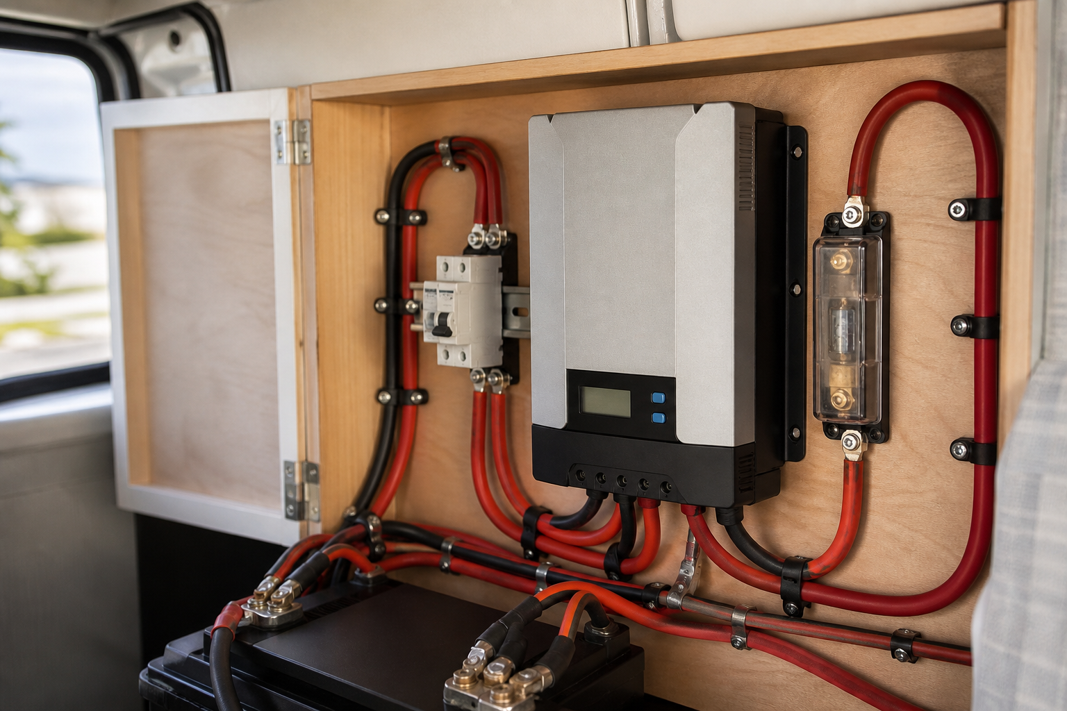
- Plan placement: protect the wire at its source. Every positive conductor should have its overcurrent protection as close as practical to the point where it receives power — the battery terminal for the main cable, the busbar for feeds leaving the busbar, and the fuse block for branch circuits. Marine practice keeps this distance to a matter of inches wherever feasible, because any cable between the source and the fuse is unprotected. Note that some circuits receive power from both ends in a fault scenario (for example, a cable between a battery and a busbar fed by charge sources); protect at the higher-energy end at minimum, and at both ends where practical. Solar-array wiring is the one direction-specific case: fusing between panels and controller is generally required only when three or more strings are in parallel, because two paralleled strings cannot push more than one string’s fault current into another — check your panel’s “maximum series fuse rating” on its label and follow it.
- De-energize and mount the hardware. Disconnect solar input first, then shore power, then the battery negative cable, then positive. Confirm zero volts with your multimeter at every point you will touch. Mount fuse holders and breakers on a rigid, non-conductive surface with fasteners that will not loosen under road vibration; leave the fuses themselves out of the holders for now. Orient holders so covers can be installed and fuses replaced without disassembling surrounding wiring. Troubleshooting: if a holder’s studs sit closer to grounded metal than the width of your smallest screwdriver, relocate it — a dropped tool across a battery-side stud is a dead short.
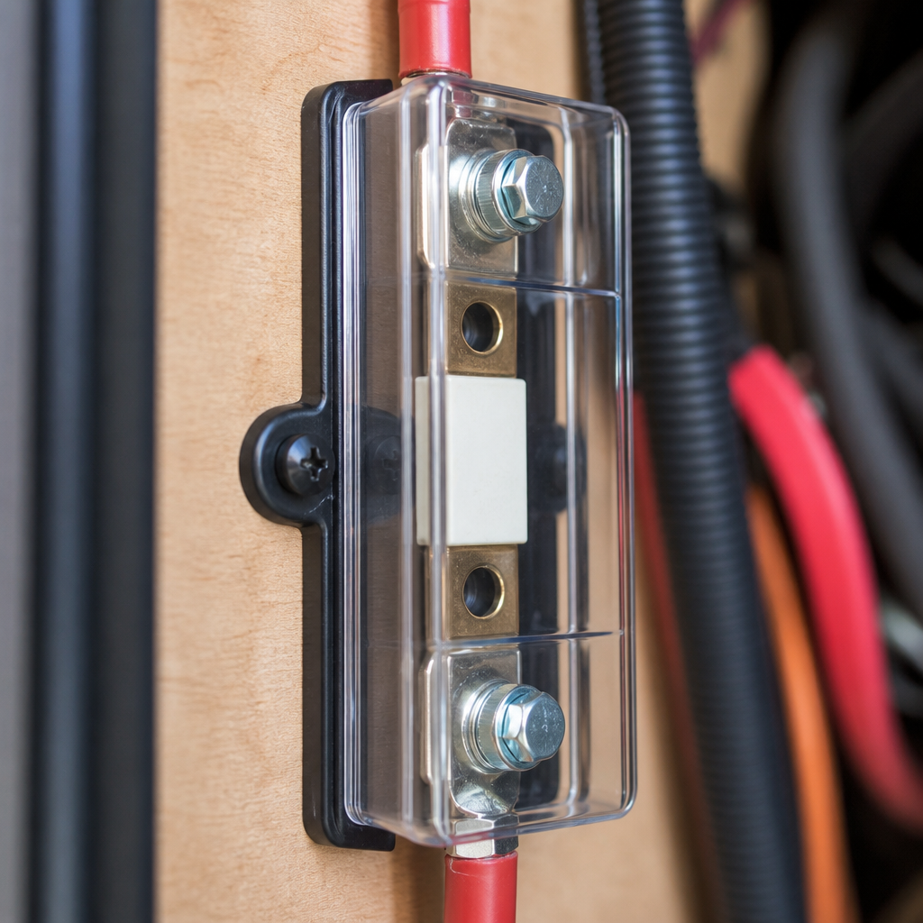
- Make the terminations correctly. Cut cables to length, strip without nicking strands, and crimp marine-grade heat-shrink lugs with a crimper matched to the lug size — pliers and hammer crimps fail under vibration and heat cycling. Seat lugs flat on the fuse-holder studs with no washers between the lug and the fuse element’s contact surface, stack hardware in the order the holder manufacturer specifies, and torque every nut to the value printed in the holder or breaker documentation. Under-torqued connections are the leading cause of heat damage at fuse holders; over-torqued studs crack the fuse body or strip threads. Apply terminal protectant to exposed metal after torquing. Troubleshooting: if a lug rotates on the stud after torquing, the stud is undersized for the lug hole — replace the lug with the correct bore size rather than adding washers.
- Install fuses and energize progressively. Insert fuses starting furthest from the battery and working back, with all loads switched off. Connect battery positive, then negative, then re-enable charge sources. Turn on one circuit at a time and verify normal operation. With each major load running, measure voltage across each fuse holder (positive lead on one stud, negative on the other): a healthy connection shows only millivolts of drop. A reading of several tenths of a volt indicates a poor crimp, loose nut, or corroded contact. Troubleshooting: if a fuse blows the instant you insert it with all loads off, you have a dead short downstream — disconnect the far end of that cable, check continuity to ground with the multimeter, and inspect the run for chafed insulation at every clamp and panel penetration before replacing the fuse.
- Load-test, label, and document. Run each circuit at its realistic maximum for several minutes and touch-test fuse holders and terminations — warm is acceptable, hot is not. Label every fuse and breaker with the circuit name and the rating so the correct replacement is obvious at 11 p.m. in a campground. Update your wiring diagram with final gauges, lengths, fuse types, and ratings, and store spare fuses of every size used in the rig. Troubleshooting: if a fuse blows repeatedly under normal load but the wiring checks clean, re-verify your continuous-current measurement at full load — an underestimated draw (a compressor start surge, a pump against high pressure) means you need to re-run the 125% math and possibly upsize both fuse and wire together.
Safety Considerations
- Never oversize protection to “stop nuisance blows.” A fuse rated above the wire’s ampacity converts every overload into a potential fire. If a correctly measured circuit keeps blowing its fuse, the fix is bigger wire or a smaller load, never a bigger fuse on the same wire.
- Treat battery banks as always live. There is no breaker upstream of a battery. Remove metal jewelry, use insulated tools, and cover the battery positive terminal whenever you are working near it. Lithium banks in particular can deliver fault currents high enough to weld tools instantly.
- Match interrupt ratings to the battery. A fuse that cannot interrupt the bank’s short-circuit current can arc over and continue conducting after it “blows.” For large lithium banks, use a fuse family with a high AIC rating (Class T is the usual choice) as the main protection.
- Use DC-rated devices only. DC arcs do not self-extinguish the way AC arcs do. Breakers, fuses, and switches must carry a DC voltage rating at or above your system voltage, and polarized breakers must be wired in the marked direction.
- De-energize in the correct order. Disconnect solar before the battery so the charge controller is never powered from the panel side alone, then shore power, then negative, then positive. Reverse the order when re-energizing.
- Ventilate and protect yourself. Lead-acid batteries vent hydrogen; work with compartments open and no sparks nearby. Wear safety glasses when torquing terminals — a slipped tool across battery terminals can spray molten metal.
If any part of this work is beyond your comfort level, have a qualified RV or marine electrical technician review the installation before energizing.
FAQs
- What determines the correct fuse size for an RV circuit? The fuse must be rated above the circuit’s maximum continuous current multiplied by 1.25, and at or below the ampacity of the wire it protects. If those two requirements conflict, the wire is too small for the load and must be upsized; the fuse rating is never raised beyond the wire’s ampacity to resolve the conflict.
- Does the fuse protect the appliance or the wire? The fuse exists to protect the wire from overheating during an overload or short circuit. Most appliances contain their own internal protection, so your job when sizing circuit protection is to keep the conductor safe, which is why wire ampacity is the hard upper limit on fuse rating.
- Where should fuses be placed in an RV electrical system? Each fuse belongs on the positive conductor as close as practical to the point where that conductor receives power — the battery terminal for the main cable, the busbar for feeder cables, and the fuse block for branch circuits. Any length of cable between the power source and the fuse is unprotected, so keep that distance to inches wherever possible.
- What size fuse do I need for my RV inverter? Apply the same rule as every other circuit: multiply the inverter’s maximum continuous DC input current by 1.25, and confirm the cable’s ampacity is at or above the result. Most inverter manuals publish a recommended fuse size and cable gauge for exactly this reason, and the manufacturer’s specification should take precedence as long as it stays within your wire’s rating.
- Do I need a fuse between the solar panels and the charge controller? Generally only when three or more strings are wired in parallel, because that is when combined fault current from the other strings can exceed one string’s wiring capacity. Check the “maximum series fuse rating” printed on your panel’s label and follow it; many installers also add a DC breaker on the array input regardless, since it doubles as a convenient service disconnect.
- What is the difference between ANL, MRBF, and Class T fuses? All three serve mid-to-high current DC circuits, but they differ mainly in interrupt rating and mounting style. Class T fuses have the highest interrupt capability and are preferred as the main fuse on lithium battery banks, MRBF fuses mount directly on a battery terminal and suit smaller banks, and ANL fuses are an economical choice for busbar-fed circuits where fault current is more limited.
Conclusion
Sizing and installing fuses and breakers in an RV comes down to a repeatable discipline applied to every positive conductor in the system: measure or look up the true maximum continuous current, multiply by 1.25, confirm the wire’s ampacity is at or above the chosen rating, pick a fuse family whose interrupt rating suits the location, and mount the protection as close to the power source as physically practical. The paperwork phase — the worksheet, the datasheets, the clamp-meter readings — matters more than the wrench work, because a perfectly torqued connection on a wrongly sized fuse is still a fire risk. Take the arithmetic from your own equipment’s documentation rather than from generic charts of “typical” loads, and let the manufacturer’s recommended fuse size settle any doubt where one is published.
Before you call the job finished, run this verification checklist
- ☐ Every positive conductor in the system has overcurrent protection at its power-source end, with no unprotected runs longer than a few inches
- ☐ Every fuse or breaker rating is at or above 1.25 × the circuit’s measured continuous current and at or below the wire’s published ampacity
- ☐ The main battery fuse’s interrupt rating meets or exceeds the bank’s short-circuit current capability per the battery datasheet
- ☐ All terminations are crimped with proper lugs, torqued to specification, and show only millivolts of drop under full load
- ☐ No fuse holder or breaker is more than warm to the touch after several minutes at realistic maximum load
- ☐ Every device is labeled with its circuit name and rating, spares of every size are stored aboard, and the wiring diagram is updated to match what is actually installed
- ☐ Covers are fitted over all exposed studs, and nothing conductive can fall across battery-side terminals
Re-check torque and terminal temperatures after the first few hundred miles of travel — road vibration reveals marginal connections quickly, and a five-minute inspection is the cheapest insurance your electrical system will ever get.
Spot an error or an outdated detail in this guide?
Report it