RV Solar Not Charging? How to Troubleshoot & Fix It Fast
On this page

TL;DR
- Start: Rule out the trivially obvious before touching a meter.
- Then: Test panel open-circuit voltage against the label.
- Finish: Decide: repair, replace, or call a professional.
Introduction
A voltage difference of just 0.4V between your charge controller’s battery terminals and the battery posts themselves is enough to point you at a corroded lug, a failing inline fuse holder, or an undersized cable — and that single comparison measurement solves a surprising share of “RV solar not charging” complaints. Troubleshooting a solar charging system is not guesswork; it is a chain of measurements taken in a specific order, from the panel on the roof down to the battery terminals, until the point of failure reveals itself as a voltage that is missing, wrong, or dropping where it shouldn’t.
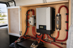
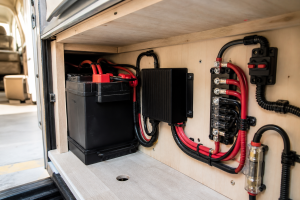
The system you are diagnosing has only four functional blocks: the panels (the source), the wiring and overcurrent protection (the path), the charge controller (the brain), and the battery bank (the destination). When charging stops, one of those blocks has failed, been disconnected, or been misconfigured. The most common culprits reported by RV owners and technicians are mundane: a battery disconnect switch left in the wrong position, a blown inline fuse between the controller and battery, a loose or corroded MC4 connector, a charge controller programmed for the wrong battery chemistry, or a battery so deeply discharged that the controller refuses to wake up and charge it.
Before you climb on the roof or start pulling fuses, gather your system’s actual specifications. Generic numbers will mislead you; your own numbers will convict the guilty component.
Scroll sideways to see every column.
| Factor | How to Determine It | Why It Matters |
|---|---|---|
| Panel rated open-circuit voltage (Voc) and max-power voltage (Vmp) | Read the spec label on the back of each panel, or pull the manufacturer datasheet by model number | Your multimeter reading in full sun should land near the label’s Voc; a reading far below it flags a damaged panel or bad connection upstream |
| Panel wiring configuration (series, parallel, or series-parallel) | Trace the roof wiring or check the installer’s diagram; series strings add voltage, parallel strings add current | Determines what “correct” voltage looks like at the controller input — a series pair should read roughly double one panel’s Voc |
| Charge controller type and settings | Model label on the controller; note whether it is PWM or MPPT, and check the programmed battery-type profile in the menu or app | A controller set to the wrong chemistry (e.g., lead-acid profile on a lithium bank) can undercharge, refuse to charge, or fault out |
| Battery chemistry and nominal voltage | Battery label or datasheet — flooded lead-acid, AGM, gel, or lithium (LiFePO4) | Each chemistry has different resting voltages, charge setpoints, and low-voltage cutoff behavior, which changes what a “healthy” reading is |
| Battery resting voltage and state of charge | Measure at the battery posts with a multimeter after the battery has rested (no charge or load) for a period; compare against your battery manufacturer’s state-of-charge chart | A deeply discharged or sulfated battery may refuse charge or trip controller protection, mimicking a solar failure |
| Fuse and breaker locations and ratings | Installer documentation, or physically trace the positive cable from controller to battery and from panels to controller | A blown inline fuse anywhere in the chain silently breaks the circuit while everything else looks normal |
| Presence and wiring of battery disconnect or transfer switches | Owner’s manual and physical inspection — determine whether the disconnect isolates the battery from the solar controller circuit | On many RVs, flipping the disconnect “off” also disconnects the charge controller from the battery, stopping charging entirely |
| Cable gauge and one-way run length (controller to battery) | Read the AWG printed on the cable jacket; measure the run with a tape measure | Feeds the voltage-drop formula so you can decide whether a low reading is resistance loss or a genuine fault |
What You’ll Need
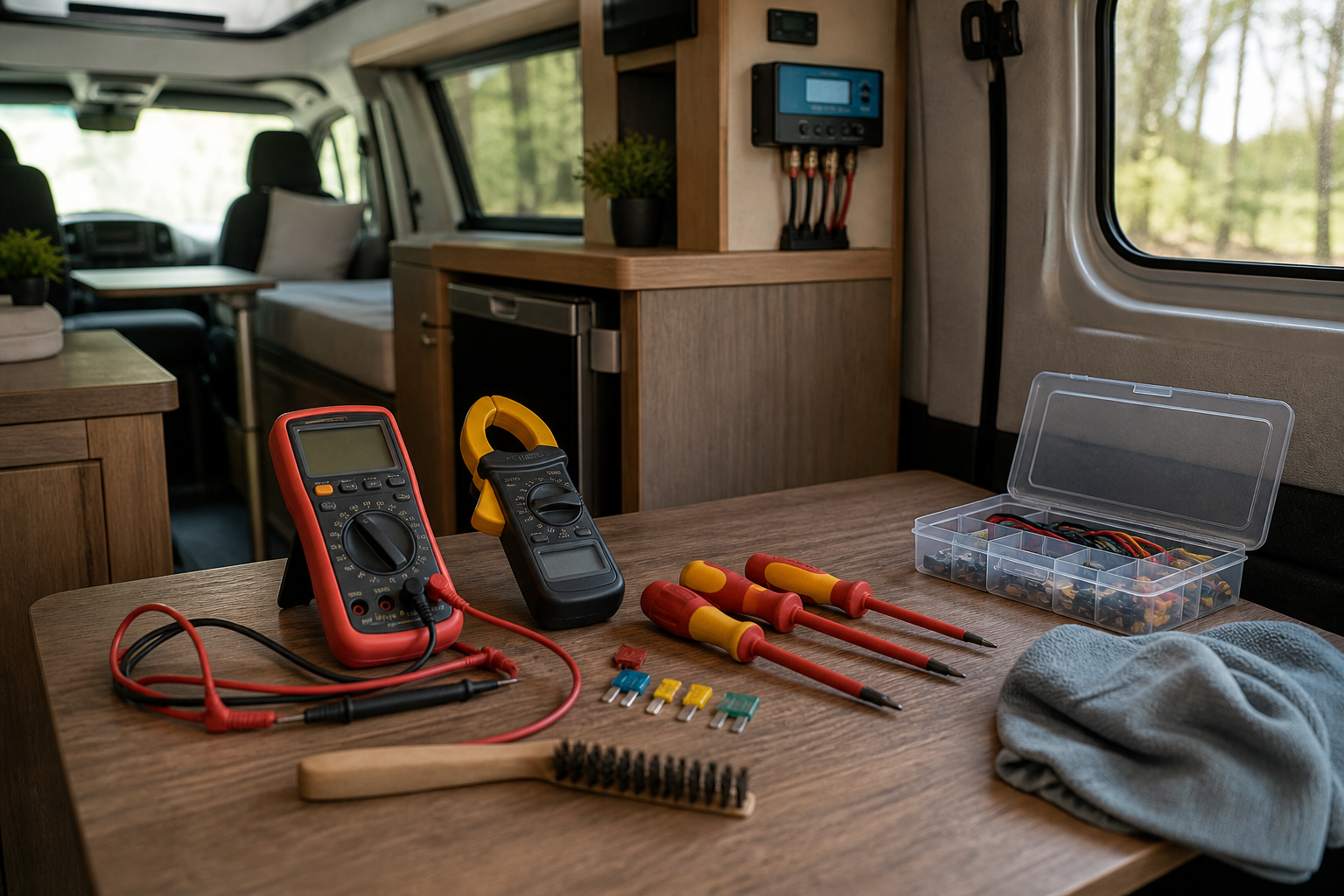
- Digital multimeter capable of reading DC voltage (at minimum) — a model that also reads DC current is a bonus
- DC clamp meter (optional but extremely useful for reading charging current without breaking the circuit)
- Your panel, controller, and battery datasheets or spec labels (photograph the labels if they are hard to reach)
- Screwdrivers and appropriate wrenches/sockets for terminal lugs and fuse holders
- Spare fuses matching every rating used in your system (inline MC4 fuses, ANL or MEGA fuses, blade fuses in the DC panel)
- MC4 disconnect tool and, ideally, an MC4 crimping tool with spare connectors
- Wire brush, fine sandpaper, or terminal cleaning tool plus dielectric grease or anti-corrosion spray
- Cardboard or an opaque blanket large enough to cover a panel (to safely de-energize the array while working on connectors)
- Sturdy ladder rated for your weight, plus non-slip footwear for roof work
- Notebook or phone to log every voltage reading, with location and time — the pattern of readings is the diagnosis
- Flashlight or headlamp for inspecting dark compartments, roof entry glands, and battery bays
Tracing the Fault: A Panel-to-Battery Diagnostic Sequence
- Rule out the trivially obvious before touching a meter. Confirm the panels have unobstructed sun — not filtered light through a tree canopy, not a shadow from your roof AC unit or a raised satellite antenna crossing part of the array. Partial shading on even one panel of a series string can collapse output for the whole string. Wipe off dust, pollen, road film, and bird droppings; a visibly dirty panel can lose meaningful output. Then check every switch: the battery disconnect (on many rigs, “off” isolates the battery from the entire 12V system including the charge controller), any solar-specific breaker or switch the installer added, and — on rigs with automatic transfer switches — verify the coach is actually seeing the power source you think it is. Owners on RV forums repeatedly discover that a disconnect flipped during storage was the whole problem. Also confirm the season and sun angle are realistic: flat-mounted panels in winter at high latitude may produce a fraction of their summer output even in “full sun.”
- Read the charge controller’s display or status lights first. The controller is the only component that already knows what both the panels and the battery are doing, so interrogate it before dismantling anything. Note the reported PV input voltage, battery voltage, charging current, charge stage (bulk, absorption, float), and any error codes or blinking-light patterns. Look the codes up in the controller manual — common faults include battery over-voltage, battery low-voltage disconnect, PV over-voltage, over-temperature, and reverse polarity. Two informative patterns: if the controller shows healthy PV voltage but zero amps and the battery voltage is already at the float setpoint, the system may be working correctly and the battery is simply full. If the controller shows zero PV voltage in bright sun, the fault is upstream (panels, roof wiring, or PV-side fuse). If the display is completely dark, the controller has lost its battery-side connection — most controllers power themselves from the battery, not the panels — which points you at the battery-side fuse or disconnect.
- Measure battery voltage directly at the battery posts. Set your multimeter to DC volts and place the probes on the battery posts themselves — not the cable lugs, not a distribution bus. Compare the reading to your battery manufacturer’s state-of-charge chart for your specific chemistry. For lead-acid chemistries, a resting battery near full charge sits noticeably higher than a deeply discharged one, and a battery drawn far below its healthy range may be sulfated and unwilling to accept charge. Lithium (LiFePO4) batteries add a quirk: their internal battery management system (BMS) will disconnect the cells entirely after a low-voltage or low-temperature event, and a BMS in protection mode can present near-zero volts at the terminals, which makes some charge controllers refuse to start charging at all. If your battery reads drastically low or zero, the battery — not the solar — may be the root problem, and you may need to wake the BMS or bench-charge the battery per the manufacturer’s recovery procedure before solar charging can resume.
- Compare controller battery-terminal voltage against battery-post voltage. With the system attempting to charge, measure DC volts across the controller’s battery output terminals, then immediately measure across the battery posts. Record both. The two readings should be close; a large gap means resistance in the path between them — a corroded lug, loose set screw, failing fuse holder, or undersized cable. Here is the math that turns your two readings into a verdict. Worked example — assumed values for illustration only, not defaults: suppose the controller terminals read 14.2V while the battery posts read 13.6V during charging, and your clamp meter shows 15A flowing. The drop is 14.2 − 13.6 = 0.6V. Effective circuit resistance is R = V ÷ I = 0.6 ÷ 15 = 0.04 ohms. Now compare against what the cable alone should contribute: published resistance tables give ohms per foot for each AWG size, and total conductor length is twice the one-way run (out on the positive, back on the negative). If the calculated cable resistance for your gauge and length is far below 0.04 ohms, the excess resistance lives in a connection or fuse holder — go find it by measuring voltage drop across each individual junction while current flows. Any single connection dropping more than a few hundredths of a volt under load deserves cleaning and re-torquing.
- Test panel open-circuit voltage against the label. This is the definitive “is the panel alive” test. Cover the array or work in early light for safety, disconnect the PV input at the controller or at an accessible MC4 pair (never yank MC4s apart under load — the DC arc damages contacts), then uncover the panels, aim your meter at the disconnected PV leads, and read DC volts in direct sun. Compare against the spec label. Worked example — assumed values for illustration only, not defaults: if your panel’s label lists a Voc of 22.5V and you measure 21–22V on a bright day, the panel is healthy — Voc readings normally land near but slightly below the label figure depending on temperature and irradiance. Two panels in series with that label should read roughly double, in the neighborhood of 43–45V. If a series pair reads only about half the expected total, one panel or one inter-panel connection has failed; test each panel individually to isolate it. A reading of zero volts means an open circuit — a broken conductor, unseated connector, or blown PV-side fuse — somewhere between your probes and the cells. A reading that is present but drastically low (well under the label Voc in genuine full sun) suggests internal panel damage such as cracked cells, a failed bypass diode, or delamination.
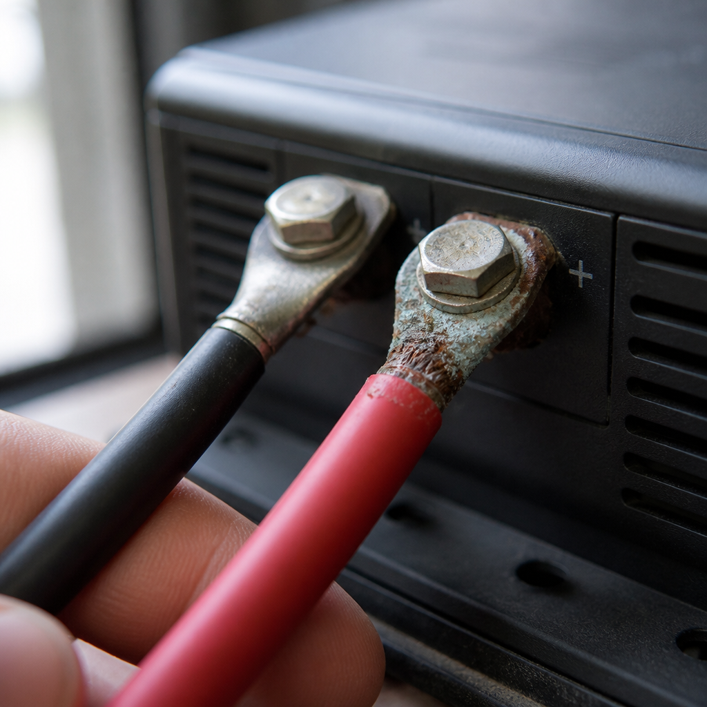
- Inspect and test every fuse, breaker, and connector in the path. Work the circuit end to end: MC4 connectors at each panel, the roof-entry gland (a notorious spot for chafed insulation and water intrusion), any combiner or junction box, the PV-side fuse or breaker, the controller terminals, the battery-side inline fuse (often an ANL, MEGA, or MIDI fuse close to the battery), and finally the battery lugs. Do not trust a visual fuse inspection — fuses can fail invisibly, and fuse holders can corrode internally while the fuse itself is fine. Instead, with the circuit energized, measure DC volts across each fuse: a good fuse drops essentially zero volts; a blown fuse shows the full circuit voltage across it. Alternatively, with the circuit fully de-energized, pull each fuse and check continuity. Wiggle-test every connector; MC4s that were hand-assembled without a proper crimp tool are a leading failure point, and heat discoloration or melted plastic around any terminal is a red flag demanding replacement, not just cleaning. Clean corroded battery terminals down to bright metal, re-torque to spec, and protect with dielectric grease.
- Verify the charge controller’s programming, then perform a proper reset. Confirm the battery-type profile matches your actual chemistry — a controller left on a gel or flooded profile may hold voltage setpoints too low to meaningfully charge a lithium bank, and a lithium profile on lead-acid can trigger faults. Check absorption and float voltage settings against your battery datasheet, verify any temperature-sensor setting (a disconnected temperature probe on some models skews charging voltage), and confirm the controller’s rated PV input voltage was never exceeded by your string configuration. Then reset the controller in the correct order, which matters because most controllers must detect the battery before the panels: (1) disconnect or cover the PV input first, (2) disconnect the battery side, (3) wait a minute or so for internal capacitors to discharge and the logic to fully power down, (4) reconnect the battery side first, (5) reconnect the PV input last. Watch the boot sequence for error codes. If the controller still shows good PV voltage and good battery voltage but delivers zero charging current with no plausible explanation (battery genuinely not full, settings correct, no faults), the controller itself is the prime suspect — internal MOSFET failures produce exactly this “shows power but won’t charge” symptom.
- Confirm actual charging current with a clamp meter and validate under load. Clamp a DC current meter around the positive cable between controller and battery (clamp one conductor only — clamping both cancels the reading to zero). In good sun with a partially discharged battery, you should see meaningful current flowing; the exact figure depends on your array size, sun conditions, controller type, and charge stage, so judge it against your own system’s history rather than a universal number. A useful cross-check on MPPT controllers: expected battery-side current ≈ (PV voltage × PV current) ÷ battery voltage, minus conversion losses — if the controller’s displayed input power and output current don’t roughly reconcile through that formula, the display or the controller is lying. Then apply a modest DC load (turn on some lights) and confirm the controller responds by increasing current. If everything checks out here, your “not charging” problem may actually have been a full battery in float mode all along, or an intermittent fault — in which case repeat the key measurements at different times of day and after driving over rough roads, since vibration-induced intermittent connections are common in RVs.
- Decide: repair, replace, or call a professional. Tally your findings. Blown fuses, corroded terminals, failed MC4s, and wrong controller settings are owner-fixable in an afternoon. A dead panel confirmed by the Voc test usually means replacement, since field repair of internal cell damage is rarely worthwhile. A controller with persistent error codes, heat damage, or the “voltage in, nothing out” signature should be replaced — and this is a sensible moment to confirm the replacement’s specs match your array’s string voltage and your battery chemistry. Escalate to a qualified RV or solar technician if you find melted insulation or scorching anywhere (a fire-risk indicator), if the fault involves the transfer switch or converter interacting with the solar circuit, if your system runs at higher string voltages you’re not comfortable working on, or if repeated fuse-blowing suggests a short circuit you cannot locate. Document your final working readings — PV Voc, controller input voltage, charging current in known conditions, and battery-post voltage — as a healthy baseline for the next time something misbehaves.
Safety Considerations
- Solar panels are always live in daylight and cannot be switched off at the source. Cover the array with cardboard or an opaque blanket, or work at dawn/dusk, before disconnecting PV-side wiring.
- Never disconnect MC4 connectors or fuse holders under load — DC arcs are sustained and hot, and they pit contacts, burn fingers, and can ignite nearby material. Kill the load or cover the panels first.
- Batteries store enormous fault current. Remove metal jewelry and watches before working near terminals, insulate wrench handles, and never let a tool bridge the posts. Flooded lead-acid batteries also vent explosive hydrogen — no sparks or flames in the battery bay.
- Follow the correct connect/disconnect sequence for charge controllers (battery first on, PV first off) to avoid damaging the controller or exposing yourself to unregulated PV voltage.
- Roof work causes more RV-repair injuries than electricity does. Use a rated, stable ladder, keep three points of contact, avoid wet or dew-covered roof membranes, and never step near skylights or vent covers.
- If you find melted insulation, scorched terminals, or a burning smell anywhere in the system, de-energize it (cover panels, disconnect the battery) and do not restore power until the damaged section is replaced — heat damage indicates a genuine fire risk, not a cosmetic issue.
This information is general guidance; always follow your equipment manufacturer’s instructions and consult a qualified technician when in doubt.
FAQs
- Why is my RV solar not charging even in full sun? The most common causes are a blown inline fuse between the controller and battery, a battery disconnect switch left in a position that isolates the controller from the battery, loose or corroded MC4 connectors, a charge controller programmed for the wrong battery chemistry, or a battery so deeply discharged that the controller or a lithium BMS has entered protection mode. Working through the panel-to-battery measurement sequence in this guide will isolate which of these applies to your rig.
- How do I test if my solar panel is actually working? Disconnect the panel from the controller (safely, with the panel covered), then measure its open-circuit voltage with a multimeter in direct sunlight and compare the reading to the Voc printed on the panel’s spec label. A healthy panel reads near its label value; a reading of zero indicates an open circuit in the panel or its leads, and a reading far below the label in genuine full sun suggests internal cell or diode damage.
- How do I reset my RV solar charge controller? Cover or disconnect the panel input first, then disconnect the battery connection, wait roughly a minute for the controller to fully power down, then reconnect the battery side first and the panels last. Most controllers must detect the battery before the array, so reversing this order can cause faults or, on some models, damage.
- Why does my controller show voltage but no charging amps? This usually means one of three things: the battery is already full and the controller is correctly holding at float, the controller’s battery-type settings don’t match your chemistry so it thinks charging is complete, or high resistance in the wiring, a fuse holder, or a terminal is choking current flow. Compare voltage at the controller terminals versus the battery posts under load — a significant difference points to a resistance problem you can locate junction by junction.
- Can a blown fuse really stop all solar charging? Yes — a single blown fuse anywhere in the chain (PV-side inline fuse, the battery-side ANL or blade fuse, or a fuse in the DC distribution panel) opens the circuit completely while everything else looks normal. Test fuses with a meter rather than by eye, since fuses can fail invisibly and fuse holders can corrode internally even when the fuse itself is intact.
- Can a bad battery prevent solar charging? Absolutely. A sulfated lead-acid battery may refuse to accept meaningful current, and a lithium battery whose BMS has tripped on low voltage or cold temperature can read near-zero volts at its terminals, which prevents many charge controllers from powering up or initiating a charge. In these cases the battery must be recovered per the manufacturer’s procedure before solar charging can resume.
Conclusion
Troubleshooting RV solar that isn’t charging comes down to a disciplined chain of measurements: confirm sun and switches, interrogate the controller’s display, measure battery-post voltage, compare it against the controller’s output terminals, verify panel open-circuit voltage against the label, and prove every fuse and connector with a meter rather than your eyes. Each reading either matches your system’s documented specs — in which case you move to the next link — or it doesn’t, and you’ve found your fault.
The pattern of failures is predictable. Disconnect switches and blown battery-side fuses account for a large share of “dead” systems; corroded terminals and hand-crimped MC4 connectors cause most of the intermittent ones; wrong controller settings explain the systems that charge weakly or stop early; and genuinely failed panels or controllers, while less common, announce themselves clearly through the Voc test and the voltage-in-nothing-out signature respectively. The voltage-drop formula (R = V ÷ I) turns any suspicious gap between two readings into a concrete resistance figure you can hunt down junction by junction.
Once your system is charging again, spend ten minutes on prevention: log your healthy baseline readings, re-torque and grease the battery terminals, seal and strain-relieve the roof entry, and put a seasonal panel cleaning and connector inspection on your maintenance calendar. Know your battery chemistry’s quirks — especially lithium BMS protection behavior and lead-acid’s intolerance of deep discharge — and verify the disconnect switch position every time the rig comes out of storage. A solar system that gets a five-minute checkup a few times a year almost never leaves you diagnosing a dead battery bank in a remote campsite.
Spot an error or an outdated detail in this guide?
Report it