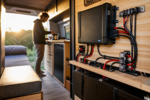
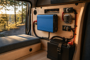
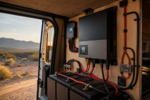
How to Wire an RV Inverter Safely: Step-by-Step
On this page
TL;DR: Quick Summary
- Gather tools and safety gear: Collect tools, materials, and safety gear before opening any panel or junction box.
- Follow the sequence in order: Follow the wiring and mounting sequence in order — skipping ahead often means rework.
- Test before closing up: Power up and test each connection before closing covers or energizing the full system.
Introduction
Divide continuous inverter watts by your battery voltage, then divide again by inverter efficiency, and you get the single most important number in this entire project: the maximum DC current your cables, fuse, and battery terminals must carry. On a 12V system, that current is large — roughly ten times what the same load would draw on the 120V AC side — which is exactly why RV inverter wiring fails far more often on the battery side than on the AC side. Undersized DC cables overheat, missing fuses turn a short circuit into a fire, and long cable runs starve the inverter of voltage until it shuts down under load.
Wiring an RV inverter safely is not complicated, but it is unforgiving of shortcuts. The job breaks down into a handful of decisions you must make with your own numbers, not someone else’s: how much continuous power your inverter is rated for, how far it will sit from the batteries, how you will feed AC into the coach without backfeeding shore power, and how the chassis will be grounded. Every one of those answers comes from your equipment — the inverter datasheet, your battery bank configuration, and a tape measure run along the actual cable path in your rig.
Before touching a wrench, work through the table below and fill in the values for your own setup. Do not copy numbers from forums or from other people’s installs; two rigs with the “same” inverter can need completely different cable gauges depending on run length and battery chemistry.
Scroll sideways to see every column.
| Factor | How to Determine It | Why It Matters |
|---|---|---|
| Inverter continuous power rating (W) | Read the manufacturer datasheet or the label on the inverter case — use the continuous rating, not the surge rating, for cable and fuse sizing | This sets the maximum sustained DC current the wiring must carry; everything downstream is sized from it |
| Inverter surge rating (W) | Datasheet; usually listed as “peak” or “surge” power for a few seconds or milliseconds | Determines whether motor-start loads (compressors, pumps) will trip the inverter, and influences fuse type selection |
| System DC voltage (12V, 24V, or 48V) | Count your batteries and check how they are wired (series vs. parallel); confirm with a multimeter at the bank terminals | Current halves each time voltage doubles, dramatically changing cable gauge requirements |
| Inverter efficiency (%) | Datasheet; typically listed as peak efficiency and efficiency at rated load | Real DC current is higher than the ideal calculation because the inverter itself consumes power |
| One-way cable run length (ft) | Measure the actual routing path from battery positive terminal to inverter with a tape measure — follow the real route, not a straight line | Voltage drop is proportional to total circuit length (out and back); longer runs need heavier cable |
| Your actual AC loads (W each) | Read the nameplate on each appliance, check its datasheet, or measure with a clamp meter or plug-in watt meter while it runs | Confirms your inverter is sized correctly and tells you what you can run simultaneously |
| Battery bank continuous discharge limit (A) | Battery datasheet — lithium batteries list a BMS continuous discharge rating; lead-acid banks are limited by capacity and wiring | An inverter that demands more current than the bank can deliver will cause shutdowns or BMS trips |
| Fuse or breaker rating (A) | Calculate: continuous DC current × 1.25, rounded up to a standard fuse size, and confirm cable ampacity exceeds the fuse rating | The fuse protects the cable, not the inverter — it must blow before the cable overheats |
| AC integration method | Decide between a transfer switch, an inverter/charger with built-in transfer relay, or dedicated inverter-only outlets | Prevents dangerous backfeeding into shore power and protects the inverter from incoming grid power |
What You’ll Need
- Inverter (pure sine wave strongly recommended for sensitive electronics) with its manufacturer datasheet and installation manual
- Marine-grade or welding-style fine-strand copper battery cable, sized per your voltage-drop calculation (gauge determined in the procedure below)
- Class T fuse, ANL fuse, or MRBF terminal fuse with matching fuse holder, rated per your calculation — Class T is preferred for large lithium banks because of its high interrupt rating
- Tinned copper cable lugs sized to your cable gauge and stud diameters, plus adhesive-lined heat-shrink tubing
- Hydraulic or hammer-style lug crimper appropriate for large-gauge cable (pliers-style crimpers are inadequate)
- Digital multimeter and, ideally, a DC clamp meter for load verification
- Automatic transfer switch rated for your RV’s shore power service, or an inverter/charger with an internal transfer relay, or a dedicated outlet plan
- Grounding wire sized per the inverter manual for chassis bonding
- Battery disconnect switch (if not already installed) and insulated tools
- Cable clamps, grommets, loom, and mounting hardware for securing runs through the RV structure
- Tape measure, wire strippers or cable cutters rated for heavy gauge, torque wrench or driver for terminal hardware
- Fire extinguisher rated for electrical fires, kept within reach during testing
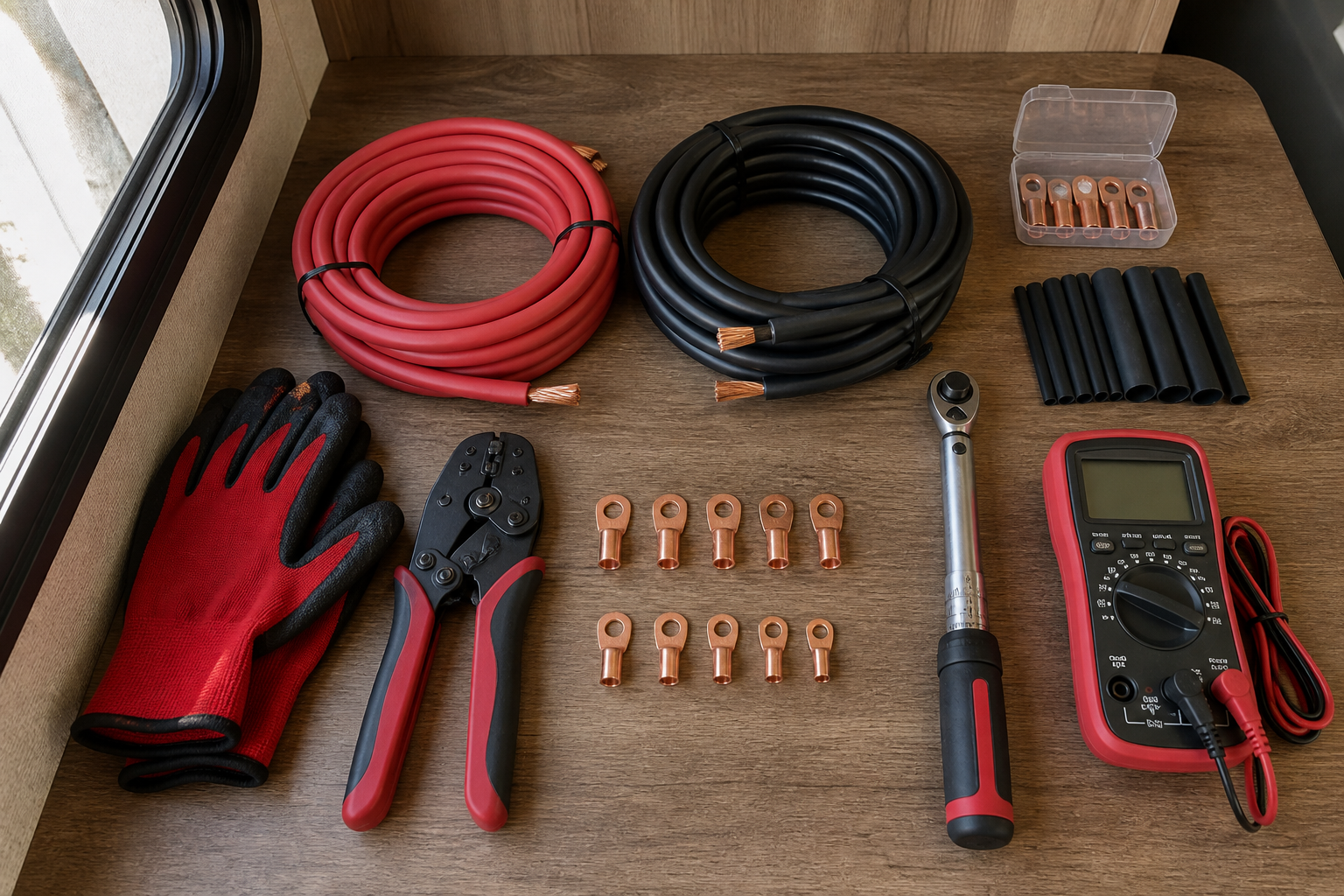
Sizing, Mounting, and Wiring the Inverter Circuit
- Calculate your maximum DC current and audit your loads. Start with the formula: DC amps = inverter continuous watts ÷ battery voltage ÷ inverter efficiency. Pull the continuous wattage and efficiency figures from your inverter’s datasheet, and confirm your bank voltage with a multimeter. Worked example — assumed values for illustration only, not defaults: suppose your datasheet lists a 2,000W continuous rating and 85% efficiency at full load on a 12V bank. Then 2,000 ÷ 12 ÷ 0.85 ≈ 196A of DC current at full output. That single number drives cable gauge, fuse rating, and battery bank requirements. Separately, walk through your rig and record the nameplate wattage of every appliance you actually intend to run on inverter power — read the label on each device or measure it with a plug-in watt meter, because two microwaves or two coffee makers can differ substantially. Confirm the sum of loads you’d run simultaneously stays comfortably under the inverter’s continuous rating, and that any motor or compressor loads fall within the surge rating.
- Measure the cable run and size the DC cable for voltage drop. With power still off, choose the inverter’s mounting location (see next step) and measure the actual routing path from the battery positive terminal to the inverter’s DC input — around corners, through bulkheads, along the real route. The general goal in RV installs is to keep this run as short as practical, ideally just a few feet, because voltage drop grows with both current and length. Use the formula: voltage drop = 2 × length (ft) × current (A) × cable resistance (Ω per ft), where the factor of 2 accounts for the round trip through positive and negative conductors. Aim to keep total drop under about 2–3% of system voltage at full load. Look up the resistance per foot for candidate gauges on a standard wire resistance chart, plug in your measured length and calculated current, and choose the gauge that meets both the voltage-drop target and the ampacity requirement (the cable’s ampacity must exceed your fuse rating). Worked example — assumed values for illustration only: continuing the 196A example over a 4 ft one-way run, 2/0 AWG copper (roughly 0.000078 Ω/ft) gives 2 × 4 × 196 × 0.000078 ≈ 0.12V of drop — about 1% on a 12V system, which passes. The same current over a 15 ft run would drop roughly 0.46V and would push you toward 4/0 AWG cable or a relocated inverter. When in doubt, go one size heavier and follow the largest gauge your inverter manual recommends.
- Mount the inverter near the batteries — but never directly above them. Choose a dry, ventilated location within your target cable-run distance of the battery bank. Mount the inverter to a solid surface (wall or shelf) with clearance around its cooling fans and vents per the manual — typically several inches on the vented sides. Do not mount the inverter in a sealed battery compartment with flooded lead-acid batteries: charging lead-acid batteries vent hydrogen gas, and the inverter’s relays and fans can provide an ignition source. Lithium banks don’t off-gas, but the inverter still needs airflow and protection from moisture and road debris. Orient it so the DC terminals face the shortest path to the batteries.
- Build and install the fused positive cable first — fuse close to the battery. The fuse’s job is to protect the cable, so it must sit within inches of the battery positive terminal, before the cable disappears into walls or compartments. Size it at roughly 125% of your calculated continuous DC current, rounded up to the next standard fuse size, then verify your chosen cable’s ampacity exceeds the fuse rating — if it doesn’t, upsize the cable, never the fuse logic. Worked example — illustrative assumptions carried forward: 196A × 1.25 ≈ 245A, so a 250A Class T fuse is a sensible choice, paired with cable whose ampacity rating exceeds 250A. Cut the cable to length, strip it, crimp on properly sized tinned lugs with a hydraulic crimper, and seal each crimp with adhesive-lined heat shrink. Tug-test every lug. Mount the fuse holder securely to a solid surface near the battery. Do not install the fuse element itself yet — leave the holder open or the fuse out until final connection.
- Connect the DC cables to the inverter, then to the battery bank — positive last. Verify your battery disconnect is off. Route both cables along the planned path, protecting them with grommets wherever they pass through metal or wood and securing them with clamps every foot or so to prevent chafing from road vibration. Connect the negative cable at the inverter, then at the battery bank’s negative terminal (on a bank with a shunt-based battery monitor, connect on the load side of the shunt so the monitor sees inverter current). Connect the positive cable at the inverter, then at the fuse holder’s load side, and finally attach the fuse holder’s battery side to the positive terminal. Torque all terminal hardware to the values specified in the inverter and battery manuals — loose high-current connections generate heat and are a leading cause of melted terminals. Expect a spark when you finally insert the fuse or make the last positive connection; that’s the inverter’s capacitors pre-charging and is normal, though some installers add a pre-charge resistor step to soften it.
- Wire the AC output through a transfer switch, inverter/charger relay, or dedicated outlets. You have three safe options, and you must pick exactly one — never plug the inverter’s output into the RV’s shore power inlet or wire it in parallel with shore power. Option A: an automatic transfer switch installed ahead of your AC distribution panel (or ahead of a small sub-panel of inverter-fed circuits) that selects between shore power and inverter output, with shore power typically given priority. Option B: an inverter/charger with a built-in transfer relay, which passes shore power through when connected and switches to inverting when unplugged — the simplest wiring for whole-coach integration. Option C: dedicated outlets wired only to the inverter, completely separate from the shore power system — the simplest and safest option for a basic travel trailer setup. Whichever you choose, one critical rule applies: the RV’s converter/charger must never be fed by the inverter, or you create a loop where the battery powers the inverter, which powers the charger, which “charges” the battery at a heavy net loss until the bank is drained. If you feed the main panel, either move the converter to a non-inverter circuit or switch its breaker off when inverting. All AC wiring must use appropriately rated conductors and strain relief, and if you are not fully confident on the AC side, this is the step to hand to a qualified RV technician or electrician.
- Ground the inverter chassis to the RV grounding system. Locate the chassis ground lug on the inverter case and run a ground wire — sized per the inverter manual, generally in proportion to your DC cable size — to a clean, bare-metal point on the RV frame or the rig’s established grounding bus. Remove paint at the attachment point, use a star washer for bite, and protect the connection against corrosion. This bond ensures that a fault energizing the inverter case has a low-resistance path to trip protection rather than through a person. Also review the neutral-ground bonding behavior in your inverter manual: many inverters bond neutral to ground internally when inverting and lift that bond on shore power, and your transfer arrangement must not create a second bond point.
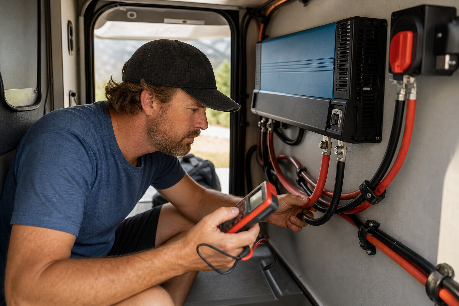
- Perform a staged power-up test with a meter in hand. Double-check every connection, confirm no tools are resting on terminals, then insert the fuse. Turn on the battery disconnect and verify DC voltage at the inverter’s input terminals matches battery voltage — a significantly lower reading indicates a bad crimp or loose connection. Switch the inverter on with no load and confirm it powers up cleanly. Verify AC output voltage at the inverter outlets or the transfer switch output with your multimeter. Then apply a small resistive load and confirm stable operation. Finally, apply a load near your realistic maximum, run it for several minutes, and use your clamp meter to measure actual DC current — compare it against your Step 1 calculation. While the heavy load runs, feel (carefully, with the back of your hand) along the cables, lugs, and fuse holder: everything should be at most slightly warm. Any hot spot means a loose or undersized connection — shut down and fix it before proceeding.
- Verify transfer switching and converter behavior, then document the install. If you installed a transfer switch or inverter/charger, plug into shore power and confirm the system switches sources correctly, then unplug and confirm the inverter takes over the intended circuits. Confirm the converter/charger is not being fed by the inverter (watch your battery monitor — battery current should not spike when inverting with no loads on). Label the fuse, the disconnect, and the transfer switch, and write your calculated current, fuse size, cable gauge, and torque specs on a card stored near the inverter. Recheck all terminal torque after your first trip, since road vibration loosens hardware.
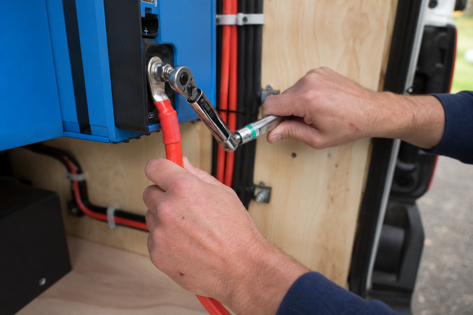
Safety Considerations
- Always fuse the positive cable within inches of the battery. An unfused DC cable that chafes through to the chassis can dump the battery bank’s full short-circuit current into the fault — with lithium banks especially, that is a fire in seconds. Use a fuse with an interrupt rating suited to your battery chemistry (Class T for large lithium banks).
- Never work on live high-current DC. Remove the fuse or open the disconnect before touching any lug, use insulated tools, and remove rings and metal watchbands — a wrench bridging a battery terminal to the chassis can weld itself in place and cause severe burns.
- Never backfeed shore power. Do not plug the inverter’s output into the shore power inlet or wire it in parallel with incoming AC. Use a transfer switch, an inverter/charger’s internal relay, or fully separate dedicated outlets so inverter output and shore power can never meet.
- Prevent the converter feedback loop. If the inverter feeds your main AC panel, ensure the RV’s converter/charger is excluded or switched off while inverting, or the battery will drain rapidly while accomplishing nothing.
- Respect ventilation and gas hazards. Give the inverter the clearance the manual requires, and never mount it in a sealed compartment shared with vented lead-acid batteries, where hydrogen gas can accumulate.
- Treat the AC side with the same respect as household wiring. Inverter AC output can deliver a lethal shock. If transfer-switch wiring, neutral-ground bonding, or panel work is outside your comfort zone, hire a qualified RV technician — the DC side is DIY-friendly, but the AC side has real code and safety implications.
This information is general guidance; always follow your equipment manuals and applicable electrical codes, and consult a qualified technician when in doubt.
FAQs
- Can I connect an inverter directly to my RV battery? Yes, connecting directly to the battery bank is the correct approach, but only with an appropriately sized fuse or breaker installed on the positive cable within a few inches of the battery terminal. Never route inverter current through the RV’s existing 12V fuse panel, which is not built for loads of that magnitude.
- What size cable do I need for my RV inverter? Cable gauge depends on your calculated DC current and your measured run length, so there is no universal answer. Run the voltage-drop calculation from the guide above with your own measured numbers. Large inverters on 12V systems commonly end up with very heavy cable such as 2/0 or 4/0 AWG, which is why short runs matter so much.
- Do I need a transfer switch for an RV inverter? You need one if you want the inverter to power your RV’s existing outlets, because the transfer switch prevents inverter output and shore power from ever being connected at the same time. If you only want a few dedicated inverter outlets separate from the shore power system, you can skip the transfer switch entirely, and an inverter/charger with a built-in transfer relay is a third option that handles switching internally.
- Should an RV inverter be left on when plugged into shore power? In most setups, no — switch the inverter off on shore power, both to avoid its idle draw and to prevent a feedback loop where the inverter powers the converter that charges the battery feeding the inverter. The exception is a purpose-built inverter/charger designed for pass-through operation, which safely passes shore power through and manages charging automatically.
- Does an RV inverter need to be grounded? Yes. The inverter chassis must be bonded to the RV frame or grounding system with a wire sized per the manufacturer’s manual, so that an internal fault trips protection instead of energizing the case. You should also verify the inverter’s neutral-ground bonding behavior so your installation doesn’t create a second bond point when on shore power.
- What are the most common inverter wiring mistakes? The most frequent and dangerous errors are undersized DC cables and missing or oversized fuses, both of which create fire risks. Close behind are cable runs that are too long (causing voltage drop and low-voltage shutdowns under load), loose lug connections that overheat, inverters mounted in unventilated or gassing battery compartments, and AC wiring that backfeeds shore power or feeds the converter in a loop.
Conclusion
Safe RV inverter wiring comes down to one calculation done honestly and a handful of rules followed without exception. Compute your real DC current from your inverter’s datasheet — continuous watts divided by bank voltage divided by efficiency — and let that number dictate everything downstream: cable gauge chosen for both voltage drop and ampacity, a fuse at 125% of continuous current mounted within inches of the battery, and a battery bank whose discharge rating can actually deliver what the inverter demands.
Keep the DC run short by mounting the inverter close to the batteries in a ventilated, dry location. Handle the AC side with exactly one integration method — transfer switch, inverter/charger relay, or dedicated outlets — so backfeeding is impossible, and make sure the converter can never be fed by the inverter it depends on. Bond the chassis to the frame, torque every lug, and verify the finished system under a real load with a clamp meter and the back of your hand checking for hot spots.
Take measurements from your own rig, pull specifications from your own equipment’s datasheets, and label your worked numbers where you can find them later. Done this way, a weekend inverter install gives you quiet, reliable AC power off-grid for years — and a wiring job you never have to worry about while you sleep.
Spot an error or an outdated detail in this guide?
Report it