How to Connect Solar Panels to an MPPT Controller
On this page
TL;DR: Quick Summary
- Check input limits first: Verify your array’s cold-weather open-circuit voltage stays within the controller’s maximum input rating.
- Match the charge profile: Set the charge profile to match your exact battery chemistry — AGM, gel, and LiFePO4 use different voltages.
- Watch the first few cycles: Monitor the first few full charge cycles and confirm the battery reaches its expected absorb voltage.
Introduction
Every MPPT charge controller has one number that cannot be negotiated: its maximum PV input voltage. Exceed it — even briefly, even on a cold morning before sunrise fully arrives — and you can permanently destroy the controller’s input stage. The second non-negotiable rule is wiring order: the battery must be connected to the controller before the solar panels, because the controller needs to detect the battery bank’s voltage to configure itself correctly. Get those two things right and the rest of the job is mostly careful crimping and methodical checking.
The steps below cover how to plan a panel configuration (series, parallel, or series-parallel) that stays inside your controller’s limits, how to size and place fuses or breakers, and how to physically connect panels to an MPPT charge controller in the correct order — battery first, PV second — then verify that the system is actually charging. The process applies equally to a small RV rooftop array, a van build, an off-grid cabin, or a portable ground-deploy kit; the voltages and currents change, but the sequence and the safety logic do not.
Wiring order matters more with MPPT than with cheaper PWM controllers. An MPPT (Maximum Power Point Tracking) controller is a DC-to-DC converter: it accepts a PV input voltage that is usually well above battery voltage, then converts that power down to the correct charging voltage and a higher charging current. Because the PV side can legitimately run at several times the battery voltage, the controller must know what battery it is charging before it sees panel power. Connect the panels first and some controllers will misidentify the system voltage, throw an error, or in worst cases suffer damage.
Battery first. Always.
What You’ll Need
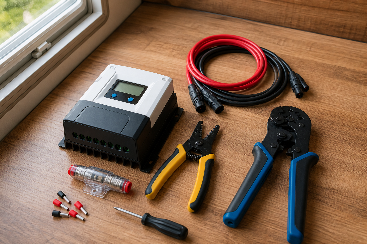
Gather everything before you strip a single wire. Half of all wiring mistakes happen because someone improvised a connector or skipped a fuse “just for testing.” Work through this preparation checklist first
- ☐ MPPT charge controller, with its manual (paper or downloaded) — you will need the max PV input voltage, max PV input current, and rated charge current
- ☐ Solar panel datasheets — specifically open-circuit voltage (Voc), short-circuit current (Isc), and the temperature coefficient of Voc
- ☐ Battery bank installed, secured, and at a known state of charge, with its charging profile documented (lithium, AGM, gel, or flooded lead-acid all charge differently)
- ☐ Digital multimeter capable of reading DC voltage and, ideally, DC current
- ☐ PV wire (UV-rated for outdoor runs) sized for your array current and cable length — aim to keep voltage drop under roughly 3% on each leg
- ☐ Battery cable sized for the controller’s maximum output charge current, kept as short as practical
- ☐ MC4 connectors and a proper MC4 crimping tool (pliers-crimped MC4s are a leading cause of hot, failing connections)
- ☐ Wire strippers, ferrule crimper and ferrules (many controllers with screw or clamp terminals specify ferrules for stranded wire)
- ☐ DC-rated fuse or breaker for the battery-to-controller line, sized per the controller manual
- ☐ DC-rated fuse, breaker, or PV disconnect switch for the panel-to-controller line
- ☐ MC4 branch connectors (for parallel wiring) if your configuration needs them
- ☐ Opaque covering (cardboard, blanket, or the panels face-down) to kill panel output while you work
- ☐ Insulated screwdrivers and basic hand tools
- ☐ Cable glands, strain relief, and mounting hardware for the controller (mounted vertically on a non-flammable surface with ventilation clearance)
Prerequisite one: confirm your cold-weather voltage math. Panel voltage rises as temperature falls, and the Voc printed on the datasheet is measured at a standard test temperature (25 °C). On a cold, clear morning your panels can exceed their rated Voc by a meaningful margin. Before you decide how many panels to wire in series, run this calculation using your own datasheet numbers
Cold-corrected Voc = datasheet Voc × [1 + (temperature coefficient of Voc × (coldest expected temperature − 25 °C))]
The temperature coefficient of Voc is a negative percentage per degree Celsius printed on your panel’s datasheet. Because it is negative, a temperature below 25 °C makes the bracketed term greater than 1, raising the voltage. Multiply the cold-corrected Voc by the number of panels in series, and that total must stay comfortably below your controller’s maximum PV input voltage. If you cannot find the coefficient, contact the panel manufacturer or leave extra headroom — many installers keep the series total at no more than 80–90% of the controller’s limit as a margin of safety.
Prerequisite two: choose series, parallel, or both. With multiple panels, you have three options, and the right one depends on your controller’s limits and your shading situation
- Series (positive of one panel to negative of the next): voltages add, current stays the same. Higher voltage lets the MPPT controller start charging earlier in the day and lets you use thinner wire for the same power, because resistive loss falls as current drops. The drawback: shade on one panel drags down the whole string, and you must verify the cold-corrected string voltage stays under the controller’s input limit.
- Parallel (positives joined together, negatives joined together, via branch connectors or a combiner box): currents add, voltage stays the same. Parallel arrays tolerate partial shading better, because a shaded panel does not choke the others. The drawback: higher current means thicker wire, and parallel arrays generally need individual string fusing once you have three or more strings.
- Series-parallel: two or more identical series strings joined in parallel. This is how larger arrays balance voltage headroom against current limits.
Mixing different panels: you can connect panels of different wattages to one MPPT controller, but mismatches cost you power. In a series string, the panel with the lowest current limits the whole string. In parallel, the panel with the lowest voltage drags the operating point down. The practical rules: for series, match the rated current (Imp) of the panels; for parallel, match the rated voltage (Vmp). If your panels differ significantly in both, the cleanest solution is a second, separate charge controller for the odd panel.
Prerequisite three: fill in your own numbers. Do not guess — copy these from your actual datasheets and manual
Scroll sideways to see every column.
| Parameter | Where to find it | Your value |
|---|---|---|
| Panel Voc (each) | Panel datasheet / label on back of panel | (from datasheet) |
| Panel Isc (each) | Panel datasheet / label | (from datasheet) |
| Temp. coefficient of Voc | Panel datasheet | (from datasheet) |
| Coldest expected ambient temperature | Local climate records for where the system will live | (your value) |
| Cold-corrected string Voc | Calculated with the formula above | (calculated) |
| Controller max PV input voltage | Controller manual / label | (from manual) |
| Controller max PV input current | Controller manual | (from manual) |
| Controller rated charge current | Controller manual | (from manual) |
| Battery bank voltage and chemistry | Battery datasheet / label | (your value) |
| One-way cable run, panels to controller | Measure it | (measure) |
With the table filled in, confirm two pass/fail checks before touching any wire: (1) cold-corrected string Voc is below the controller’s max PV input voltage with margin, and (2) total array short-circuit current (Isc × number of parallel strings) does not exceed the controller’s PV current handling per its manual. If either check fails, reconfigure the array — do not proceed hoping the controller will “handle it.”
Wiring the Battery First, Then the PV Array: The Connection Procedure
Work in this exact order. The sequence exists so that no wire you are handling is live until the moment you intend it to be, and so the controller boots correctly against the battery before it ever sees panel power.
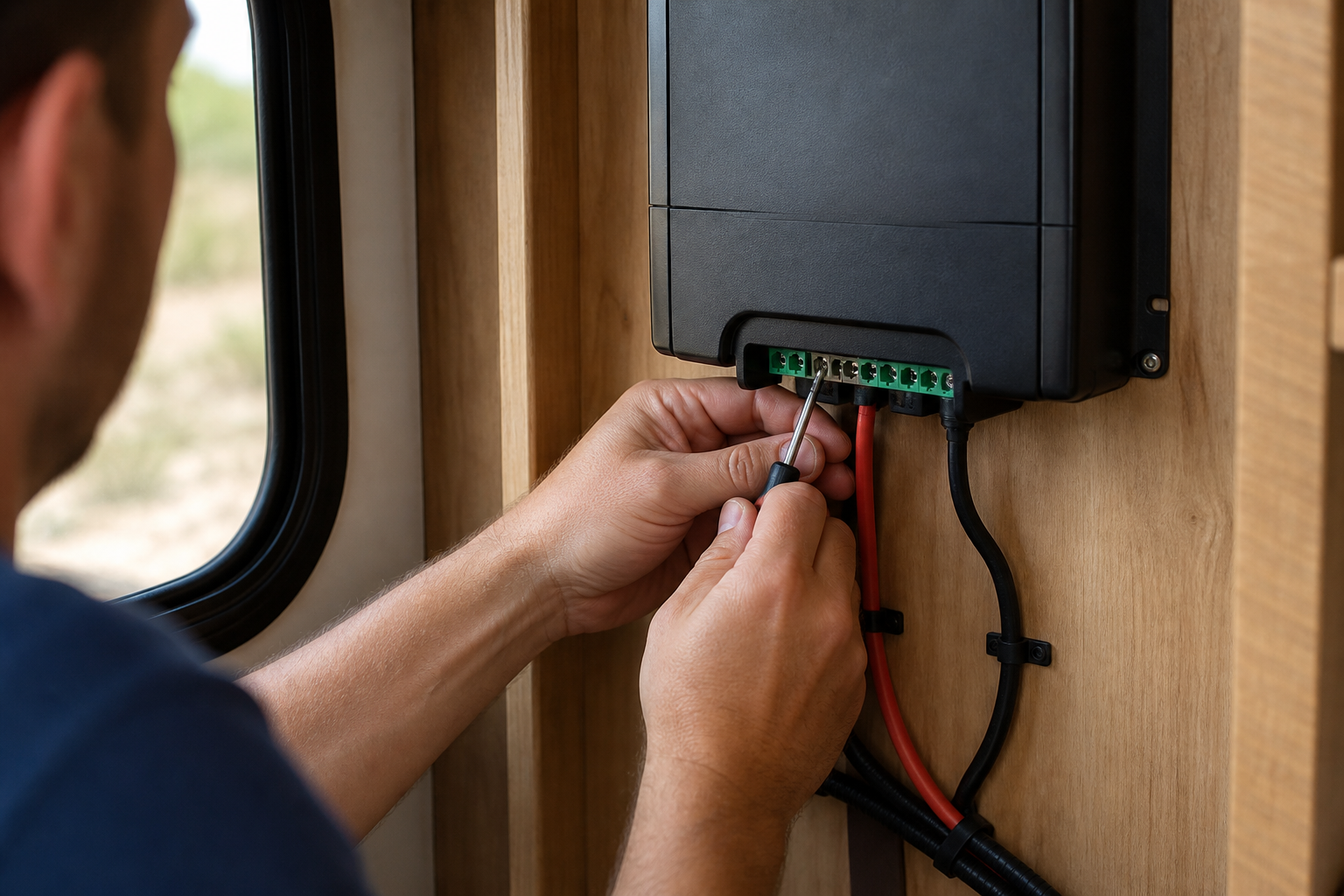
- Mount the controller and de-energize everything. Fix the controller vertically to a non-combustible surface with the clearance the manual specifies (MPPT controllers shed heat and need airflow). Cover the panels with an opaque blanket or cardboard, or leave them face-down and unplugged. Confirm any battery-side breaker is open. Troubleshooting: if your mounting location is inside a sealed cabinet with no airflow, pick another spot — thermal shutdowns and derated output are a common consequence of hot enclosures.
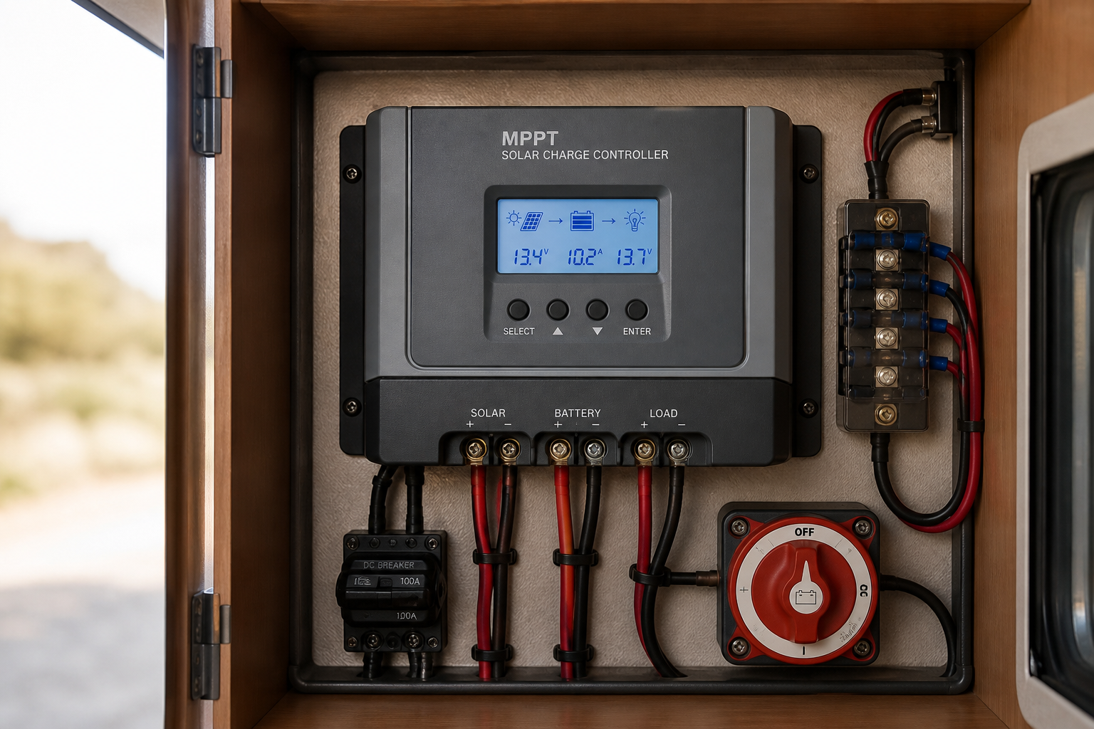
- Prepare the battery cable with overcurrent protection. Cut battery cable to the shortest practical length between the controller’s battery terminals and the battery bank (or bus bar). Install a DC-rated fuse or breaker in the positive battery line, sized per the controller manual — typically slightly above the controller’s rated charge current, and always at or below the cable’s ampacity. Place the fuse as close to the battery as practical, because the battery is the energy source that fuse protects against. Crimp ferrules or lugs as the terminal type requires.
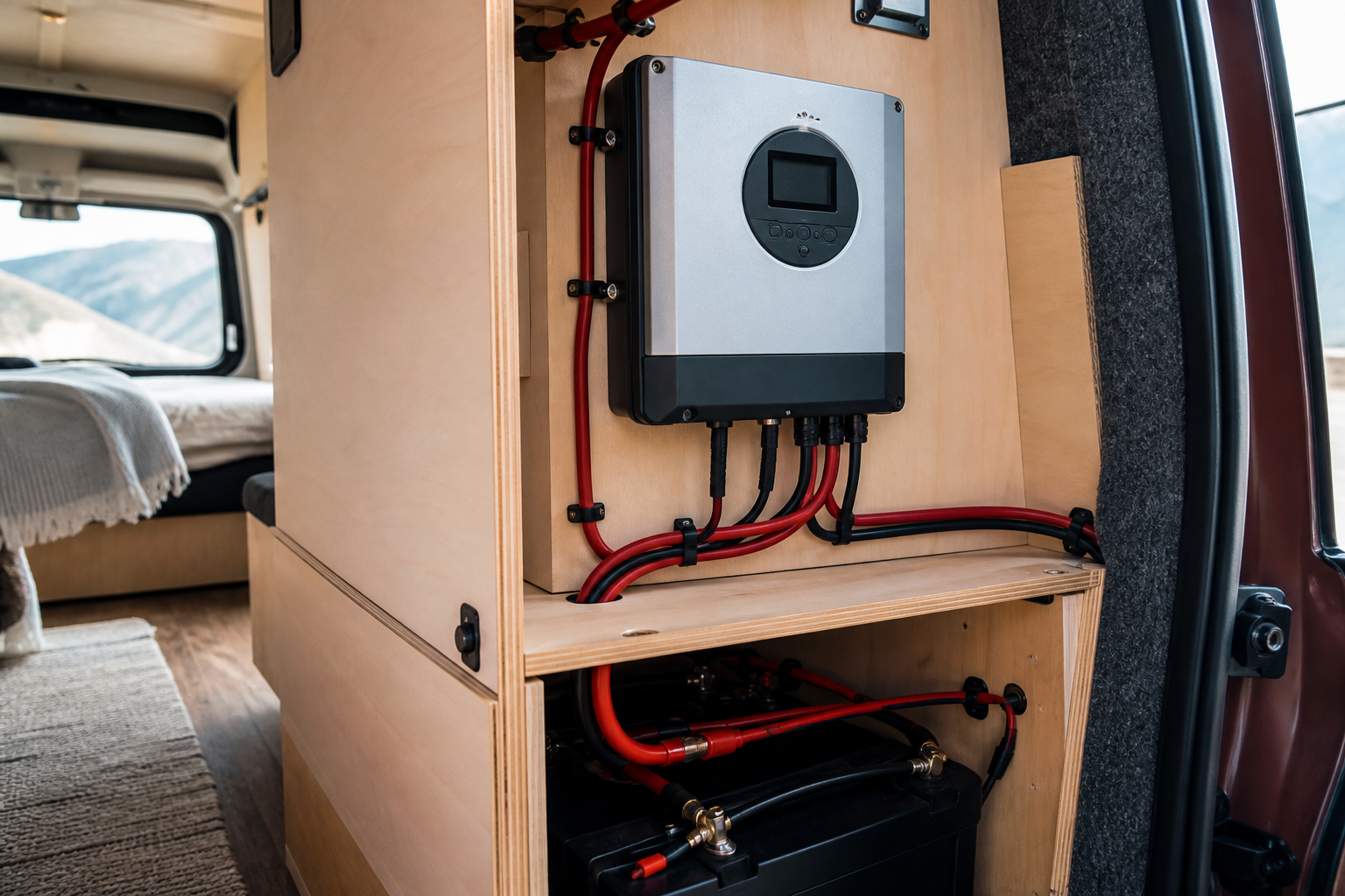
- Connect the controller to the battery — battery side first, and this connection before any PV connection. With the battery breaker open or fuse pulled, attach the negative battery cable to the controller’s battery-negative terminal and to the battery bank, then the positive cable to the controller’s battery-positive terminal and the battery-side fuse holder. Double-check polarity with your multimeter at the controller terminals before energizing: reversed battery polarity destroys many controllers instantly and is rarely covered by warranty. Then close the breaker or insert the fuse. The controller should power up from the battery.
- Verify controller settings against your battery. Using the controller’s display, buttons, or app, confirm it detected the correct system voltage (for example, a 12 V vs. 24 V bank) and set the battery chemistry and charge profile: absorption voltage, float voltage, and — for lithium — any low-temperature charging cutoff your battery manufacturer requires. Troubleshooting: if the controller shows no signs of life, check the fuse, check polarity, and check that the battery voltage is above the controller’s minimum startup voltage; a deeply discharged battery may need a bench charge before the controller will wake up.
- Build the PV array while it is dark or covered. Connect panels in your planned series or parallel configuration. For series: plug the positive MC4 of one panel into the negative MC4 of the next, leaving one free positive and one free negative at the ends of the string. For parallel: use MC4 branch connectors to join positives together and negatives together. Keep the panels covered the entire time. Troubleshooting: if an MC4 pair will not click together, you likely have two connectors of the same gender or a mis-crimped pin — never force them, and never leave a connection half-seated, because partially mated MC4s arc and overheat under load.
- Install the PV-side fuse, breaker, or disconnect. Wire a DC-rated fuse or breaker (or a dedicated PV disconnect switch) into the positive PV line between the array and the controller’s PV input, and leave it open for now. Size it above the array’s maximum short-circuit current with the margin your local code or the controller manual specifies, and at or below the wire’s ampacity. If you have three or more parallel strings, fuse each string individually per the panel datasheet’s maximum series fuse rating. Even where a fuse is arguably optional electrically, the disconnect function alone justifies it: you need a safe way to isolate the array for maintenance.
- Check PV polarity and voltage before connecting to the controller. Uncover the panels briefly and measure the open-circuit voltage across the free PV leads with your multimeter. Confirm the polarity matches your wire markings and that the reading is roughly what you calculated (number of series panels × Voc, adjusted for temperature and light conditions). Re-cover the panels. Troubleshooting: if the voltage reads near zero, check every MC4 for full engagement and inspect crimps; if it reads negative, your leads are swapped — fix the labeling now, not at the controller.
- Connect the PV leads to the controller’s PV terminals. With the PV breaker still open and panels still covered, land the PV negative on the controller’s PV-negative terminal and PV positive on the PV-positive terminal (through the fuse/breaker). Torque terminal screws firmly and tug-test every conductor. Add strain relief so cable weight and vibration — especially important in an RV or van — never load the terminals directly.
- Energize the PV side and confirm charging. Uncover the panels, then close the PV breaker. Within a few seconds to a minute, the controller’s display or app should show PV voltage, a charging current greater than zero (in daylight), and a charge state such as bulk, absorption, or float. Troubleshooting: if PV voltage shows but current is zero, the battery may simply be full (float state), the PV voltage may be too close to battery voltage for the MPPT to operate (many controllers need PV voltage several volts above battery voltage to start), or a charge setting may be wrong. If PV voltage reads zero at the controller, work backward: breaker closed? Fuse intact? MC4s seated? Measure voltage at each junction until you find where it disappears.
- Load-test and do a thermal walk-down. Let the system charge for fifteen to thirty minutes in decent sun, then carefully feel (or scan with an infrared thermometer) every connection point: controller terminals, fuse holders, MC4s, and battery lugs. Everything should be at most mildly warm. A hot connector means a loose or badly crimped joint — de-energize (PV breaker open first, then battery) and remake that connection before returning the system to service.
Safety Considerations
- Panels are live whenever light hits them. There is no off switch on a solar panel. Cover panels or work at night when making array connections, and never connect or disconnect MC4s under load — the DC arc can burn contacts and injure you.
- Batteries store enormous fault energy. A shorted battery cable can weld tools and start fires. Remove metal jewelry, use insulated tools, and never lay a wrench across battery terminals. Keep the battery-side fuse close to the battery.
- Respect the controller’s maximum PV input voltage as an absolute ceiling. Calculate cold-corrected string Voc before wiring in series; overvoltage damage is instantaneous and permanent.
- Use DC-rated protection devices only. AC-rated fuses and breakers are not designed to break a DC arc and can fail to interrupt a fault. Verify DC ratings on every fuse, breaker, and switch in the system.
- Ventilate and separate. Mount the controller with the manual’s clearance in a ventilated space, away from battery gases (flooded lead-acid banks vent hydrogen) and away from flammable materials.
- De-energize in the correct order for service: disconnect PV first (open the PV breaker or cover the panels), then the battery. Reconnect in the reverse order — battery first, PV second — every single time.
This is general guidance; always follow your controller and battery manufacturers’ manuals and applicable local electrical code.
FAQs
- Do I connect the battery or the solar panels first? Always connect the battery to the MPPT controller first, so the controller can detect the system voltage and configure its charge profile; only then connect the PV array. When disconnecting, reverse the order: PV off first, battery last.
- Do I need a fuse between the solar panels and the MPPT controller? Yes, in practice you should always install a DC-rated fuse or breaker in the positive PV line, sized above the array’s short-circuit current and at or below the wire’s ampacity. Beyond fault protection, it gives you a safe disconnect point for maintenance, and arrays with three or more parallel strings need individual string fuses per the panel datasheet.
- Can I connect two solar panels to one MPPT controller? Yes — wire them in series for higher voltage (earlier morning charging and thinner wire) or in parallel if partial shading is a concern, as long as the resulting voltage and current stay within the controller’s published input limits.
- Should panels be wired in series or parallel for an MPPT controller? Series is generally preferred with MPPT controllers because the higher input voltage extends the charging window into low light and reduces resistive wire losses for the same power; parallel is the better choice when panels will see uneven shading. Either way, verify the cold-corrected open-circuit voltage of any series string stays below the controller’s maximum PV input voltage.
- Can I mix panels of different wattages on one MPPT controller? You can, but mismatches waste power: in series the lowest-current panel limits the string, and in parallel the lowest-voltage panel pulls down the operating point. Match rated current for series strings and rated voltage for parallel strings, or use a separate controller for a significantly different panel.
- What happens if my panel voltage exceeds the controller’s maximum input? Overvoltage can permanently destroy the controller’s input electronics, and the damage typically is not covered by warranty. Because Voc rises in cold weather, always calculate string voltage at the coldest temperature your system will ever see, not at the datasheet’s standard test conditions.
Conclusion
Connecting panels to an MPPT charge controller comes down to three disciplines: plan the array so the cold-corrected string voltage and total current stay inside the controller’s published limits; wire in the correct order — battery first, then PV — with DC-rated overcurrent protection on both sides; and verify everything with a multimeter before energizing rather than after something smokes. Series wiring rewards you with earlier charging and thinner cable, parallel wiring rewards you with shade tolerance, and either works well when the numbers come from your actual datasheets rather than guesswork. The controller does the clever power conversion; your job is simply to hand it clean, correctly-polarized, correctly-fused inputs.
Before you call the job finished, run this post-completion verification checklist
- ☐ Battery was connected before PV, and the controller correctly identified system voltage and battery chemistry
- ☐ Cold-corrected string Voc, calculated from your panel datasheet, is below the controller’s max PV input voltage with margin
- ☐ DC-rated fuse or breaker installed on the battery positive line, close to the battery, sized per the controller manual
- ☐ DC-rated fuse, breaker, or disconnect installed on the PV positive line (plus string fuses if three or more parallel strings)
- ☐ Polarity confirmed with a multimeter at both the battery terminals and the PV leads before energizing
- ☐ All MC4 connectors fully clicked together; all terminal screws torqued and tug-tested; strain relief in place
- ☐ Controller shows PV voltage, nonzero charging current in daylight, and a valid charge stage (bulk, absorption, or float)
- ☐ Thermal walk-down completed after 15–30 minutes of charging — no hot connectors, fuse holders, or terminals
- ☐ Disconnect procedure noted somewhere visible: PV off first, battery off last; reconnect battery first, PV last
Keep the filled-in parameter table and your controller settings with the system documentation. Six months from now, when you add a panel or upgrade the battery bank, those numbers — and the habit of checking them before touching a wire — are what keep a simple expansion from becoming an expensive repair.
Spot an error or an outdated detail in this guide?
Report it