RV Solar Charge Controller Sizing: Get the Right Amps
On this page
TL;DR: Quick Summary
- Check input limits first: Verify your array’s cold-weather open-circuit voltage stays within the controller’s maximum input rating.
- Match the charge profile: Set the charge profile to match your exact battery chemistry — AGM, gel, and LiFePO4 use different voltages.
- Watch the first few cycles: Monitor the first few full charge cycles and confirm the battery reaches its expected absorb voltage.
Introduction
A 40A MPPT controller on a 12V battery bank tops out at roughly 520 watts of usable solar — connect more and the extra power is simply clipped, or worse on cheap units, the controller overheats. Sizing controller amperage correctly avoids wasted panel capacity and premature failures. Below, you’ll calculate the exact amperage rating your RV system needs, verify the voltage limit, and choose between MPPT and PWM with confidence.
The sections below explain how to size rv solar charge controller amperage, with the key decision points and checks along the way.
What You’ll Need
- The datasheet or back-of-panel label for every solar panel in your array (showing rated watts, Vmp, Imp, Voc, and Isc)
- Your battery bank’s nominal voltage (12V, 24V, or 48V) and chemistry (lithium/LiFePO4, AGM, flooded lead-acid)
- A calculator or spreadsheet
- Pen and paper (or a printable worksheet) to record your array totals
- The lowest expected ambient temperature for the places you camp (for cold-weather voltage correction)
- Your planned wiring diagram — how panels will be connected in series, parallel, or series-parallel
- The datasheet for any charge controller model you’re considering, showing max output amps, max PV input voltage, and max recommended array wattage per battery voltage
- Optional: a multimeter or clamp meter to verify real panel output once installed
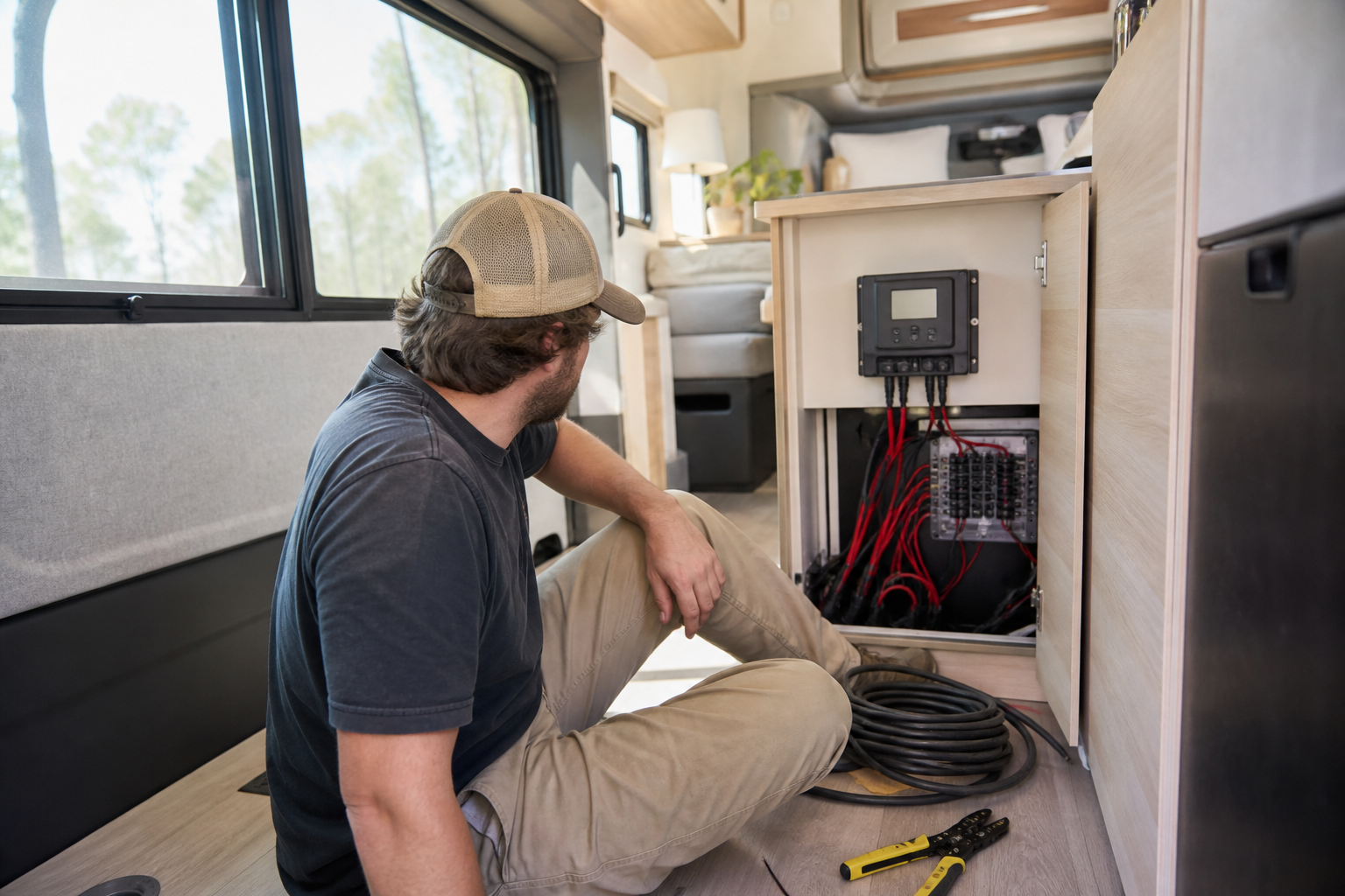
Calculating and Verifying Your Charge Controller Amperage
- Total up your solar array wattage. Add together the rated (STC) wattage printed on the label of every panel you plan to connect to this controller, including panels you intend to add within the next year or two. This total is the single most important number in the entire calculation. If you are running two separate arrays — for example, roof panels and a portable ground-deploy panel — decide now whether each array gets its own controller or whether they share one. Arrays with very different orientations or panel specs often perform better on separate controllers, and each controller is sized independently.
Use a simple worksheet like this and fill in your own values
Scroll sideways to see every column.
Panel Rated watts (from label) Voc (from label) Isc (from label) Panel 1 (your value) (your value) (your value) Panel 2 (your value) (your value) (your value) Panel 3 (your value) (your value) (your value) Array total watts (sum) — — - Confirm your battery bank’s nominal voltage. Controller output amperage is measured at the battery side, so the bank voltage is the denominator in your sizing math. Most RVs run 12V banks; larger off-grid builds increasingly use 24V or 48V because higher voltage cuts the required controller amperage dramatically for the same array wattage. If you have any plans to move to a 24V bank later, run the calculation for both voltages now — the same array needs only half the controller amps at 24V compared to 12V, which can change which controller model makes sense.
Also note your battery chemistry. Chemistry doesn’t change the amperage formula, but it determines which charge profiles the controller must support, and lithium banks in particular need a controller with a proper LiFePO4 or user-programmable profile. Lead-acid banks also benefit from temperature-compensated charging, so check whether the controller includes or accepts a battery temperature sensor.
- Apply the core amperage formula. The foundational calculation is
Controller output amps = Total array watts ÷ Battery bank nominal voltage
This tells you the maximum current the controller could theoretically push into your batteries if the array produced its full rated output. Write this number down as your “raw amps” figure.
Worked example — assumed values for illustration only, not defaults: suppose you assume a 400W array on a 12V bank. 400 ÷ 12 = 33.3 raw amps. If instead you assume the same 400W array on a 24V bank, 400 ÷ 24 = 16.7 raw amps. Notice how the higher bank voltage halves the required controller current — that relationship holds for any array size.
- Add an equipment-specific sizing margin. Panels can briefly exceed their rated output in real-world conditions — cold, clear days, “edge-of-cloud” lensing where sunlight reflects off passing clouds, and high-altitude camping can all push production above the sticker rating. Standard practice is to multiply your raw amps by 1.25
Recommended controller size = (Array watts ÷ Battery voltage) × 1.25
Continuing the illustrative example above (assumed 400W array, 12V bank): 33.3 × 1.25 ≈ 41.7 amps, which points you toward a 50A controller — or a 40A model if you accept occasional clipping of brief production peaks. Round up to the next standard controller size (common ratings are 10A, 20A, 30A, 40A, 50A, 60A, and up). Rounding down means planning to throw away power.
- Adjust the math for your controller type: MPPT vs PWM. The formula in Steps 3–4 applies directly to MPPT (Maximum Power Point Tracking) controllers, because an MPPT unit converts whatever the array produces down to battery voltage and is rated by its output current. Most manufacturers publish a “max recommended array wattage” per battery voltage for each MPPT model — always cross-check your array total against that spec.
PWM controllers work differently: they connect the array more or less directly to the battery, dragging the panel voltage down to battery voltage. That means a PWM controller only works efficiently when panel voltage closely matches the battery bank — typically nominal “12V” panels on a 12V bank — and you size it by the array’s short-circuit current (the sum of the Isc values of all parallel strings) times the same 1.25 margin, rather than by watts ÷ volts. High-voltage residential-style panels waste enormous amounts of power on PWM controllers, because everything above battery voltage is simply discarded. For most modern RV builds, especially anything above a single small panel, MPPT is the better choice: it harvests more in cold and low-light conditions, allows high-voltage series strings that reduce wire size, and simplifies sizing.
Put simply: if your panels’ Vmp sits well above your battery voltage, PWM is off the table — only MPPT can convert that extra voltage into charging current.
- Check the controller’s maximum PV input voltage against your string’s cold-weather Voc. Amperage is only half the sizing job. Every controller has a hard maximum input voltage — exceed it even momentarily and you can destroy the unit, often voiding the warranty. Add up the open-circuit voltage (Voc) of every panel wired in series to get your string Voc, then apply a cold-temperature correction, because panel voltage rises as temperature drops. Panel datasheets list a temperature coefficient of Voc (a negative percentage per °C); use it with the coldest morning temperature you realistically expect.
Illustrative Voc correction — assumed values only: a series string of three panels, each with a labeled Voc of 24.0V, totals 72.0V at the 25°C (77°F) test-standard temperature. Assuming a temperature coefficient of −0.30%/°C and a coldest expected morning of −15°C (5°F) — 40°C below the reference — the correction is 72.0 × (1 + 0.0030 × 40) = 72.0 × 1.12 ≈ 80.6V. A controller with a 100V input limit clears that with headroom; a 75V unit could be destroyed on the first frosty sunrise.
If your corrected string voltage exceeds the controller’s limit, either rewire the array into shorter series strings (more parallel groups) or choose a controller with a higher voltage ceiling.
- Decide whether to deliberately oversize. Oversizing a charge controller — buying more amperage capacity than today’s array needs — is completely safe and is often smart. The controller simply never runs at its ceiling, which means cooler operation, longer life, and room to add panels later without replacing anything. The only downsides are upfront cost and physical size. A useful rule: if you have roof space for more panels and any intention of using it, size the controller for the future array now. Conversely, modest undersizing on a quality MPPT unit isn’t catastrophic — reputable controllers limit their output to their rating and “clip” the excess — but you’re paying for panel watts you can never harvest, and sustained operation at the limit stresses cheaper units. Never rely on clipping behavior with a budget controller of unknown quality.
- Map your result onto standard controller sizes. Use your final numbers from Steps 4 and 6 and fill in a comparison for the models you’re considering. Because maximum supported array wattage scales with battery voltage, the same controller handles roughly twice the array watts on a 24V bank as on a 12V bank. As a general relationship for MPPT units: max practical array watts ≈ controller amps × battery voltage (some manufacturers allow modest over-paneling beyond this — check the datasheet).
Scroll sideways to see every column.
Candidate controller Rated output amps Max PV input voltage Max array watts @ your bank voltage (from datasheet) Fits your array? Option A (from datasheet) (from datasheet) (from datasheet) (yes/no) Option B (from datasheet) (from datasheet) (from datasheet) (yes/no) Option C (from datasheet) (from datasheet) (from datasheet) (yes/no) Worked example — assumed values for illustration only: assuming an 800W array on a 24V bank, raw amps = 800 ÷ 24 ≈ 33.3A, and with the 1.25 margin ≈ 41.7A, so a 50A MPPT controller (or a 40A unit if you accept minor clipping) fits — provided the string’s cold-corrected Voc stays under that model’s input limit.
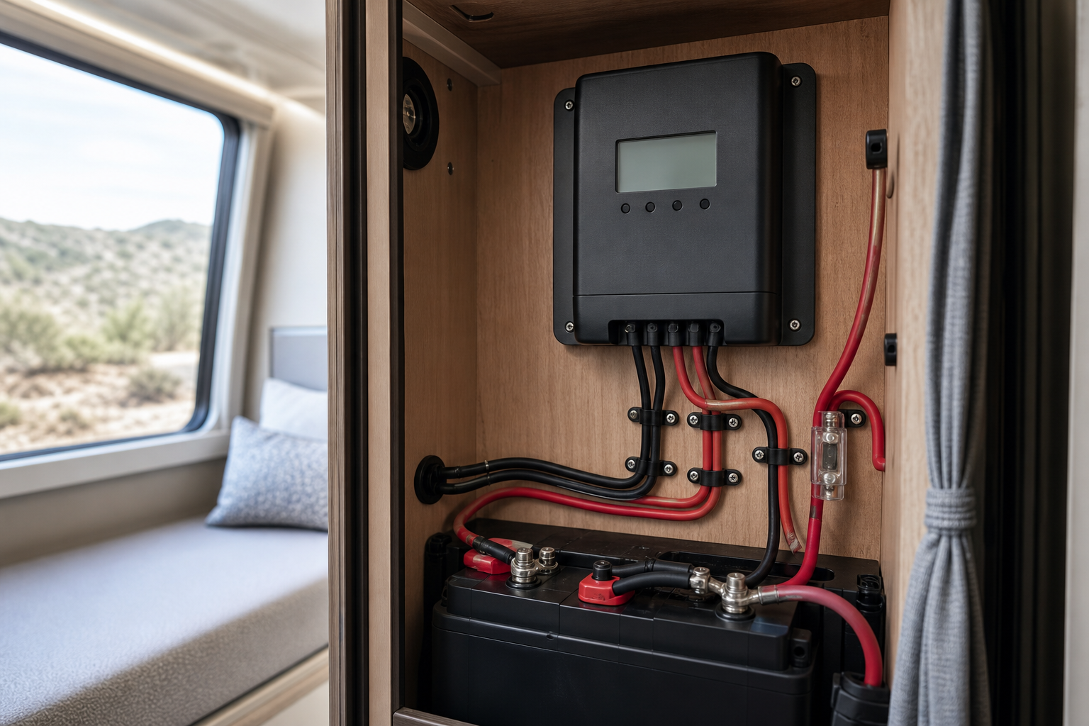
- Size the wiring, fusing, and disconnects to match the controller output. The conductor between the controller and battery bank must be rated for the controller’s full rated output current — not just today’s expected production — with an overcurrent device (fuse or breaker) sized per the controller manual, placed close to the battery. On the PV side, size wire and any string fusing to the array’s short-circuit current with the same 1.25 factor. A commonly used design target is to keep voltage drop on the controller-to-battery run under about 2–3%; use a wire-gauge (AWG) chart for your amperage and round-trip cable length.
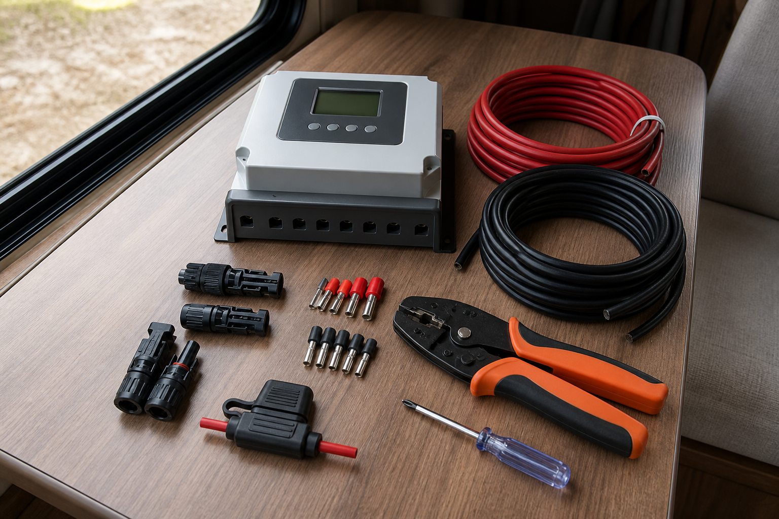 Gather your controller, correctly gauged cable, fuses, and crimping tools before wiring.
Undersized battery-side wire is one of the most common DIY failures: it creates voltage drop that confuses the controller’s charge-stage logic and generates heat at terminals. Keep the controller-to-battery run as short as practical.
- Verify real-world performance after installation. On a clear midday with batteries partially discharged (so the controller isn’t throttling in absorption or float), read the controller’s display or app. Output current should approach — but not sit continuously pinned at — the controller’s rating. Use a clamp meter on the battery cable to confirm the display is honest. If output flat-lines exactly at the controller’s maximum for long stretches on sunny days, you’re clipping and left harvest on the table; note that for your next upgrade. Also check that the controller’s reported battery voltage matches a multimeter reading at the battery terminals — a discrepancy signals voltage drop from undersized or loose wiring.
Safety Considerations
- Never exceed the controller’s max PV input voltage. Cold mornings raise panel Voc above the label rating; a string that’s “fine” in summer can destroy the controller on a frosty sunrise. Always apply the cold-temperature correction before finalizing string wiring.
- Connect the battery before the panels, and disconnect in reverse order. Most controllers must sense battery voltage first to configure themselves; energizing the PV input with no battery attached can damage many models. Follow your specific manual’s sequence exactly.
- Fuse both sides of the controller. Place an appropriately sized fuse or breaker between controller and battery (close to the battery) and a disconnect on the PV input so you can safely isolate the system for service.
- Cover panels or open the PV disconnect before wiring. Solar panels are live whenever light hits them — there is no “off switch.” Arcing DC at string voltages can cause burns and welded connectors.
- Match wire gauge to the controller’s full rated output, not today’s array. Undersized conductors overheat, melt insulation, and are a leading cause of RV electrical fires.
- Give the controller ventilation. Controllers derate or fail in hot, enclosed compartments. Mount vertically on a non-combustible surface with clearance per the manufacturer’s instructions, and never mount directly above batteries that can vent corrosive gases.
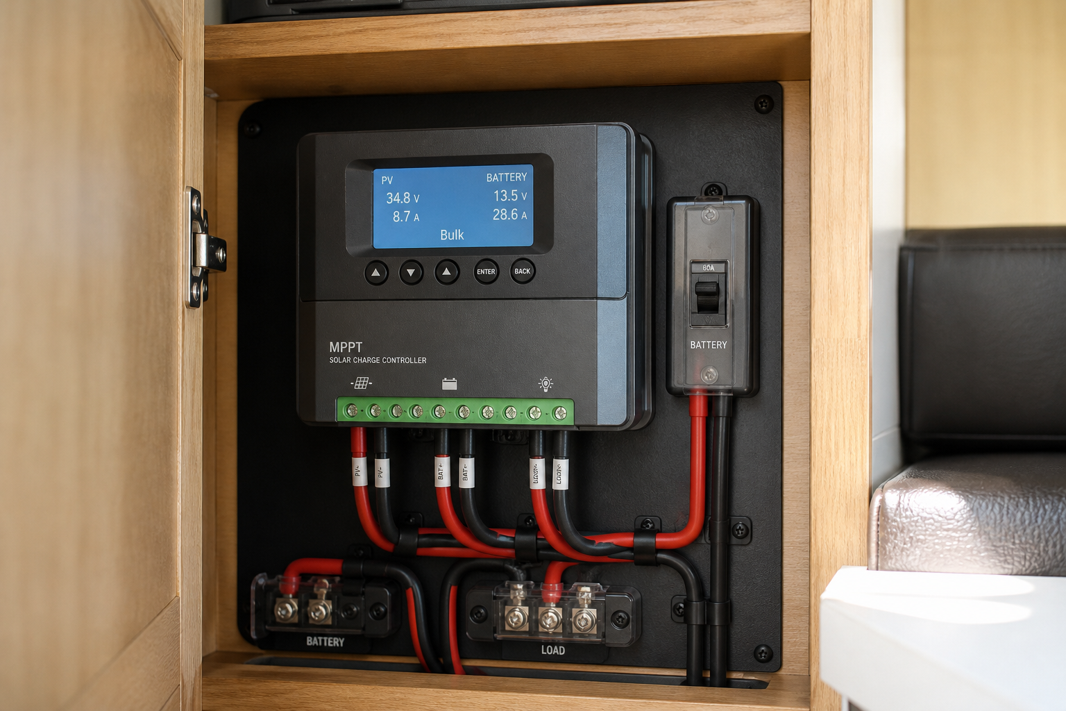 Mount the controller where airflow keeps it cool under load.
This is general guidance only — always follow your controller and battery manufacturers’ installation instructions and any applicable electrical codes.
FAQs
- How do I calculate solar charge controller amperage for my RV? Divide your total array watts by your battery bank’s nominal voltage to get raw amps, then add the manufacturer-recommended sizing margin and round up to the next standard controller size. Always cross-check the result against the manufacturer’s published maximum array wattage for your battery voltage.
- How many watts can a 40 amp MPPT charge controller handle? As a general relationship, an MPPT controller supports roughly its rated amps multiplied by battery voltage — so a 40A unit handles on the order of 480–520W on a 12V bank and about twice that on a 24V bank, depending on the specific model’s datasheet. Some manufacturers permit deliberate over-paneling beyond that figure with the excess clipped; check your unit’s manual before relying on it.
- Is it okay to oversize a charge controller? Yes — an oversized controller is completely safe, runs cooler, tends to last longer, and leaves headroom to add panels later without replacing hardware. The only real penalties are higher upfront cost and a physically larger unit.
- How many solar panels can a 30A controller handle? Work backward from the formula: 30 amps times your battery voltage gives the approximate maximum array wattage, so a 30A controller on a 12V bank supports an array in the neighborhood of 360–400W depending on the model’s spec sheet. Divide that ceiling by your individual panel’s rated wattage to get your panel count, and confirm the series string voltage stays under the controller’s input limit.
- What happens if my charge controller is too small? A quality MPPT controller will simply limit output to its rating and clip the excess, meaning you paid for solar watts you can never harvest. Cheaper or poorly designed units may overheat or fail when run continuously at their maximum, so persistent undersizing is a false economy.
- Does battery bank voltage change the controller size I need? Yes, dramatically — because amps equal watts divided by volts, the identical solar array requires only half the controller amperage on a 24V bank compared to a 12V bank. This is a major reason larger RV solar builds move to higher-voltage battery banks.
Conclusion
Sizing an RV solar charge controller comes down to one core formula plus two verifications. First, divide total array watts by battery bank voltage and multiply by 1.25, then round up to the next standard controller rating. Second, verify the controller’s maximum array wattage spec for your bank voltage on the manufacturer’s datasheet. Third — and this is the step DIYers skip most often — confirm your series string’s cold-corrected open-circuit voltage stays comfortably below the controller’s maximum input voltage, because voltage violations kill controllers while amperage shortfalls merely clip harvest.
The most common mistakes are easy to avoid once you know them: sizing for today’s array when you already plan to add panels, pairing high-voltage panels with a PWM controller, running battery-side wire too thin for the controller’s full rated output, and connecting panels before the battery during commissioning. Any one of these can waste money or hardware; all four are preventable with ten minutes of datasheet reading.
Your next steps: fill in the array worksheet with your actual panel labels, run the formula for both your current bank voltage and any future voltage you’re considering, shortlist two or three controllers whose amp and voltage specs clear your numbers with margin, and sketch the wiring and fusing plan before anything gets mounted. Get the amperage right on paper first, and the installation itself becomes the easy part.
Spot an error or an outdated detail in this guide?
Report it