How to Upgrade a WFCO WF-8955 Converter for Lithium Batteries
On this page
- 1. Find out which WF-8955 you have
- 2. Hold WFCO’s lithium profile against your battery
- 3. Check the current against the battery’s charge rating
- 4. Pick the part that fits the job
- 5. What the main board swap involves
- 6. Run the first charge and read it
- 7. Bring the other chargers back one at a time
- What WF-8955 owners ask
- Leave a note inside the door

The label beside your breakers says WF-8955. It doesn’t say which charger sits in the lower half of the box. That charger, and the battery you pair it with, decide whether going lithium costs you a replacement module or nothing at all. You’re likely to find one of three versions. The original charges the way a lead-acid charger does. The LiS version has a lithium switch on its fuse board. The Auto-Detect version chooses a profile by itself.
If yours is the original, WFCO’s fix is a single part: the WF-8955-AD-MBA, a main board that slides into the enclosure you already have. WFCO’s manual says it should be installed by an experienced, certified technician, so step 5 shows what that job involves. The model check, the battery match and the charging test need no panel work, and they’re worth doing yourself whoever holds the screwdriver.
Do you need the swap, and which part?
- Do you need it? Not if you have a WF-8955LiS or WF-8955-AD and its lithium profile suits your battery. The original holds 13.6 V and raises its target to 14.4 V only after the output current has hit the maximum.
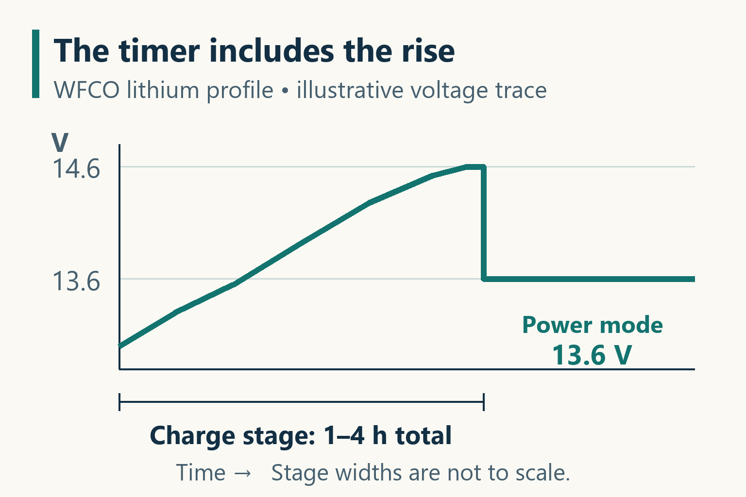
- Which part? For an original unit, WFCO’s drop-in is the WF-8955-AD-MBA. Its lithium profile aims for 14.6 V during a charge stage of one to four hours, then holds 13.6 V. It is rated 50 A on lithium and 55 A on lead-acid. Compare those numbers with your battery’s manual before ordering.
- How do you know it worked? Begin with a partly discharged bank and solar off. With the WFCO board, the voltage at the battery posts should climb toward 14.6 V and later settle at 13.6 V.
1. Find out which WF-8955 you have
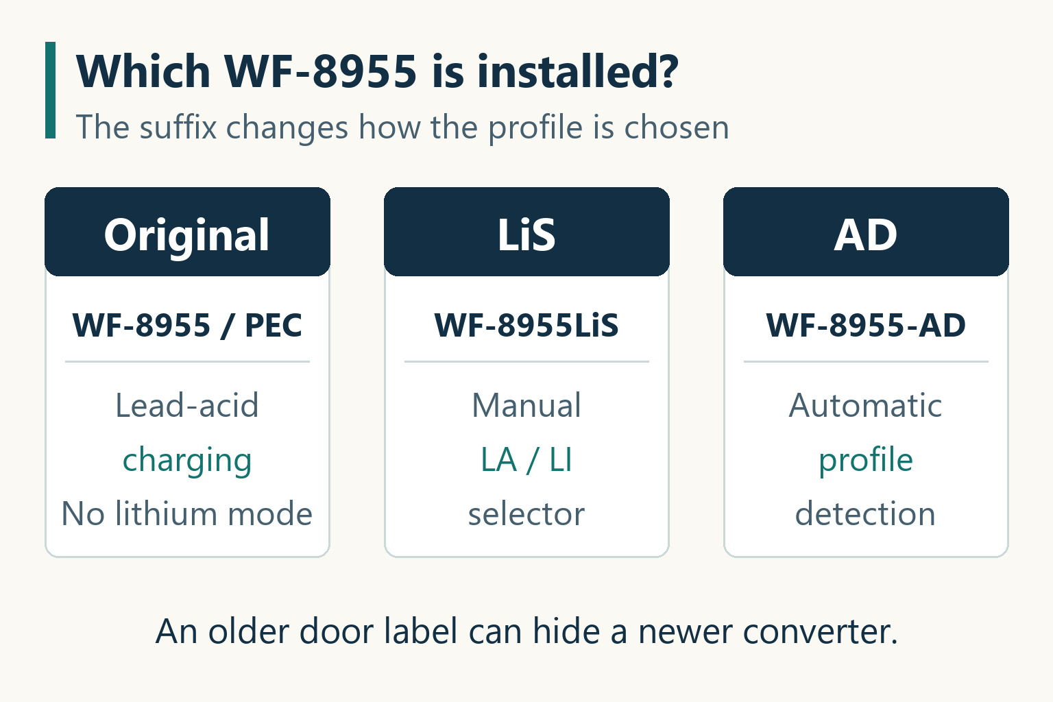
WFCO prints the model number on the front panel label next to the breakers. Read the whole number, suffix included.
- WF-8955 or WF-8955PEC, with no LiS or AD: the original three-stage converter. WFCO’s manual for this main board describes a steady 13.6 V. The target changes to 14.4 V only when the output current reaches the converter’s maximum, and goes back once the current falls to about 5 A or four hours have passed. After about 44 hours with almost no load it eases down to 13.2 V, and WFCO’s FAQ says there is no way to force the higher stage.
- WF-8955LiS: an earlier lithium generation with a slide switch on the fuse board, marked LA and LI. In LI it aims for 14.6 V in its charge stage and then holds 13.6 V. The LiS manual describes the switch and the small yellow lights beside it. If the switch is still on LA, do steps 2 and 3 before you touch it. When the profile suits your battery, unplug shore power, slide the switch to LI and plug back in.
- WF-8955-AD: Auto-Detect. It watches a charge cycle, decides whether the bank is lead-acid or lithium, and gives lithium the same 14.6 V followed by 13.6 V.
With a LiS or AD unit you may have nothing to buy. Steps 2 and 3 tell you whether that profile and its current suit your battery, and step 6 shows whether it is running. If you need a replacement, step 4 compares the options. Step 5 covers the WFCO AD-MBA swap only. A different converter needs its own installation procedure.
A label can be out of date if someone has already replaced the main board. The test in step 6 shows what the converter actually does, whatever the door says.
With the original, a lithium bank still charges. What you can’t count on is the finish. Battle Born’s BB10012 manual, for one, puts cell balancing between 14.2 and 14.6 V, and a converter resting at 13.6 V may never get there. If you’d rather measure that before buying anything, our converter check (opens in a new tab) walks through the test.
2. Hold WFCO’s lithium profile against your battery
“Lithium compatible” on both boxes doesn’t settle anything. WFCO’s manual for the Auto-Detect board gives one fixed lithium profile, so the question is whether its numbers sit inside your battery maker’s. Two batteries show how differently that can come out.
Scroll sideways to see every column.
| What to compare | WF-8955-AD-MBA | Battle Born BB10012 | Victron Lithium Battery Smart 12.8 V, 100 Ah |
|---|---|---|---|
| Charge voltage | 14.6 V target, in a charge stage of 1 to 4 hours | 14.2 to 14.6 V | 14.0 to 14.4 V, with 14.2 V recommended |
| Voltage afterwards | 13.6 V until AC power is cycled | 13.4 to 13.8 V float | 13.5 V float |
| Charge current | 50 A in the lithium profile, 55 A in lead-acid | 50 A maximum per battery | 50 A or less recommended |
On the two voltage rows the Battle Born fits. Current is a closer call, and step 3 works through it. The table leaves out timing. Battle Born asks for 30 minutes of absorption per 100 Ah of bank, and WFCO gives only the length of its whole charge stage, so those two figures can’t be set side by side. Step 6 shows how long your own bank stays near the top voltage.
The Victron battery doesn’t fit: 14.6 V is above the top of its published charge range. A battery like that needs a charger whose settings you can match to the maker’s figures.
Read the charging temperature range while the manual is open. Victron lists +5°C to +50°C (41°F to 122°F). WFCO’s manuals describe no battery temperature sensing for this converter, so the system needs working cold-charge protection of its own. Some batteries have the cutoff built in. Others, the Victron among them, report the temperature to an external BMS that has to be able to stop the charger. A heater is a different thing. It has to bring the cells back into range before any charging starts.
3. Check the current against the battery’s charge rating
Use the battery’s charge current figure, not the rating of its battery management system (BMS). The BB10012 shows the difference. Its BMS carries 100 A continuously, yet the maximum charge current is 50 A. A BMS is a safety cutoff. It doesn’t turn a charger down to a rate the cells prefer.
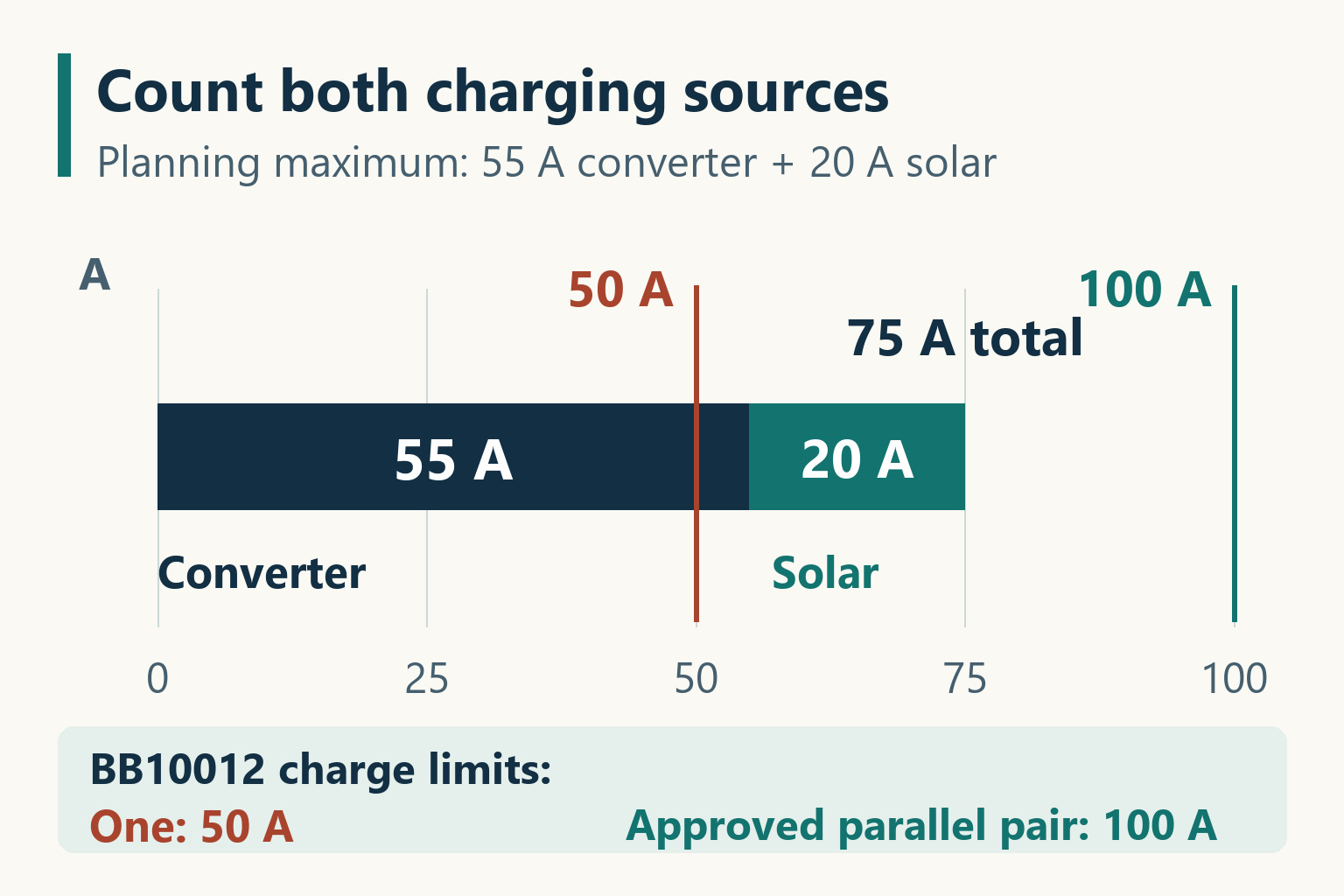
WFCO’s product sheet rates the WF-8955-AD-MBA at 50 A in its lithium profile and 55 A in lead-acid. Auto-Detect can choose the wrong profile, so plan for 55 A unless WFCO confirms a lower maximum across the profiles your unit can select. Work the numbers for your own bank:
- One 100 Ah BB10012: its 50 A limit matches the lithium rating, but the 55 A planning figure exceeds it by 5 A before any solar is added. This pairing needs a confirmed lower converter limit or a different charger or bank.
- Two in parallel: Battle Born says the limits add, so the bank accepts 100 A. That holds only where the battery maker allows it and the cabling lets both batteries share the current.
- Converter plus solar: 55 A and a 20 A solar controller make 75 A to plan for once the house loads go quiet. In the lithium profile the combined maximum is 70 A. Don’t subtract a fan or a fridge that might not be running.
Shore power and a generator feed the same converter, so count it once. WFCO documents no setting that turns the converter’s output down. If solar pushes an otherwise suitable converter over the bank’s limit, lower the solar controller’s setting or keep solar off while plugged in. If the converter alone exceeds the limit, those changes won’t solve it: choose a lower-output charger or a bank rated for the combined charge current.
4. Pick the part that fits the job
Scroll sideways to see every column.
| Part | What it is | Lithium charging | Choose it when |
|---|---|---|---|
| WF-8955-AD-MBA | Main board for the WF-8955 enclosure you already have | Auto-Detect: 14.6 V target, then 13.6 V. Rated 50 A on lithium, 55 A on lead-acid | You have the original and this profile suits your battery |
| Progressive Dynamics PD4655V | Replacement kit with its own fuse board and an adapter bracket for WFCO | Jumper marked WIZ and LI. LI holds one voltage with no later drop, at up to 55 A | You want a fixed lithium setting instead of detection |
| WF-8955-AD power center | Complete unit: breakers, fuse board and converter | The same Auto-Detect profile | The whole power center needs replacing anyway |
| WF-8955LiS already installed | Complete earlier unit with a lithium switch | Switch on LI: 14.6 V, then 13.6 V | Its profile suits your battery. Nothing to buy |
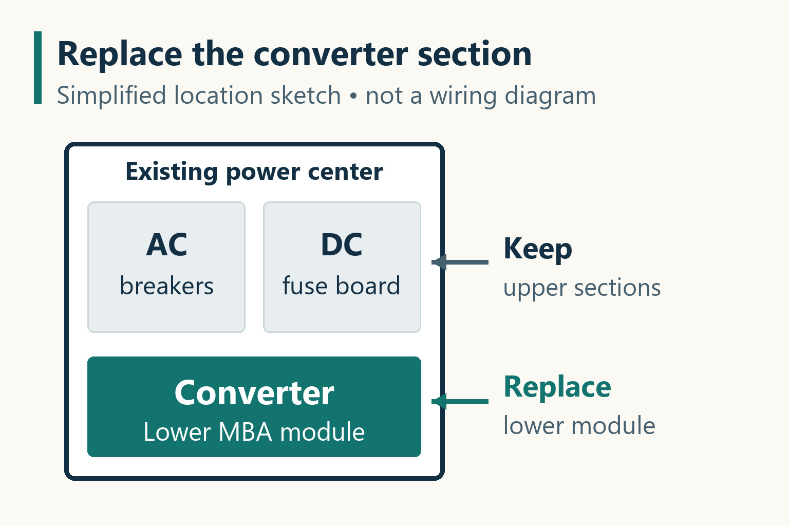
WFCO lists the WF-8955-AD-MBA as the replacement part for existing WF-8955 power centers. It goes in with two screws, three AC wires and two DC wires.
The PD4655V is the kit Progressive Dynamics names for a WF8955 going lithium. PD’s tips sheet gives the LI voltage as 14.6 V, or 14.4 V on units built after January 2023, and says the converter stays there once the bank is full. That is the opposite of WFCO’s drop to 13.6 V, so check which behavior your battery maker wants for an RV that stays plugged in. It is a 55 A charger on LI as well, which is more than a single BB10012 allows.
The kit comes with its own fuse board, and every position on it is rated for 20 A at most. A WFCO 8900-series board allows 30 A fuses at F10 and F11, often for slide-outs. PD’s tips sheet allows keeping the existing fuse board when it has fuses above 20 A. The kit’s installation guide calls for a licensed electrician or certified RV technician. Keep its steps separate from the ones below.
Two WFCO parts look right and aren’t. The plain WF-8955-MBA is the original three-stage board again. The WF-8955-REP kits are universal kits meant for other brands’ power centers, and the standard one lists lead-acid voltages in its specifications.
5. What the main board swap involves
WFCO’s instruction is plain: an experienced, certified technician installs this board. The manual’s stated concern is severe shock. The order below follows the replacement procedure in WFCO’s manuals, with the isolation and the checks written out, so you can follow the work or hand it over knowing what to ask for.
- Shut off every source and note each thing you switched. Unplug the shore cord. Stop the generator and disable its auto-start. Switch off any inverter, because it can feed the AC panel from the battery. Turn the converter’s breaker off. Shut solar down with the controller’s own sequence. Cut every link to the chassis battery: stop the engine, switch off or disconnect any DC-DC charger, isolator or combiner, and unplug the 7-way cord on a trailer. Then isolate the house bank. A battery disconnect counts only if it really cuts the feed to the power center. Otherwise remove every negative cable that leaves the bank, a separate chassis ground included, and secure them clear. The batteries, and the links between them, stay live.
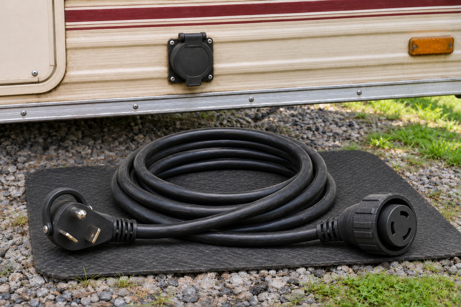
Both ends are free here and the inlet cap is shut. With a detachable cord, that keeps shore power out of the panel even if someone plugs in at the pedestal. - Take the door off. Loosen the two captive screws in its upper corners and pull the door assembly forward.
- Prove the panel is dead before touching it. Use a multimeter with probes, leads in the COM and V jacks. A non-contact tester is fine as a first pass, but Fluke’s guidance is to follow it with a contact meter, and to try that meter on a known live source of the same kind before and after. On AC volts, measure from the converter breaker’s terminal to the neutral bar and to the ground bar, then from neutral to ground. Repeat at the main breaker, where the supply comes in. On DC volts, measure VCC+ to NEG− and POS+ to NEG− on the fuse board. If the meter shows any voltage, stop. Don’t go on until you know where it comes from and a repeat test reads zero.
- Pull the two reverse-polarity fuses. On a WF-8955 they are 40 A fuses at the left-center edge of the fuse board, below the VCC+ lug. They are the link between the converter and the rest of the DC system.
- Free the two DC wires. At the upper left of the fuse board, loosen the NEG− lug with its white wire and the VCC+ lug with its red wire, without backing the screws all the way out. Press the tab at the bottom of the board, ease the board forward and pull the two wires out. The converter has a second white wire. That one is the AC neutral. It goes to the neutral bar in the breaker section, never to the fuse board.
- Free the three AC wires. Check again that the converter breaker is off. Pull the converter’s black wire out of the breaker; it ends in a metal pin. If another circuit is joined to its pigtail, disconnect that wire and move it clear. Take the green wire off the ground bar on the left and the white neutral off the neutral bar at the top.
- Slide the old board out. Remove the two screws at the front of the converter section and draw it forward, feeding the wires through the slots in the case.
- Fit the new board in reverse. Two screws first. Then neutral, ground, the black wire to the breaker and any pigtail connection. Then red to VCC+ and the DC white to NEG−. Seat the fuse board and tighten every terminal to WFCO’s torque chart. For the DC lugs that is 25 in-lb with 10 to 14 AWG wire, 32 with 8 AWG and 45 with 6 AWG. On the neutral and ground bars it is 15 to 20 in-lb for 14 AWG and 25 for 10 to 12 AWG. The breaker’s own label covers its terminal. Put the reverse-polarity fuses back, using the same type and rating.
- Close up, then restore power in mirror order. Refit the door first. Reconnect the bank the way you isolated it: every negative cable back on, or the disconnect closed. Switch the converter breaker on and plug in. Leave solar and the other chargers off for the first test.
WFCO’s product sheet calls this a ten-minute installation. The isolation and the meter checks are what take the time, and they’re the part worth watching.
6. Run the first charge and read it
Auto-Detect has to see a real charge cycle before it can choose. WFCO’s FAQ says to discharge a lithium bank far enough for the converter to enter charge mode. It gives no figure, so test after normal use, not from a full bank. Keep solar off and heavy 12 V loads to a minimum during the test. WFCO names both as things that can throw the detection off.
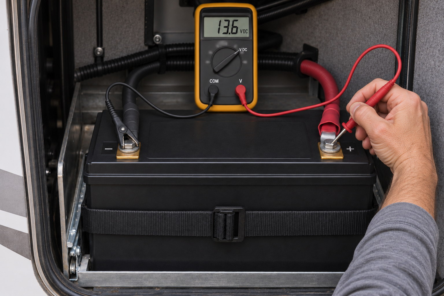
Then plug in and measure the voltage across the battery posts. That reading alone lets you follow the cycle. If you can also read current, use it: a correctly wired shunt monitor shows the bank’s net flow after the house loads. A DC clamp meter does too when it surrounds one conductor carrying all of the bank’s current; a cable serving just one parallel battery won’t give the bank total. Check whether an app reading covers one battery or the whole bank; some apps show neither current nor state of charge. If you can see the converter’s indicator light, red means the charge stage, blue means the lithium profile and green means lead-acid.
The table describes the WFCO board. A Progressive Dynamics kit on LI behaves differently: the voltage rises to its 14.4 or 14.6 V setting and stays. That is normal for that converter, and the rows about 13.6 V don’t apply to it.
Scroll sideways to see every column.
| What you see | What can explain it | Check next |
|---|---|---|
| Voltage under 14.6 V but rising | This can be normal while a depleted bank charges. Current limiting and cable drop can keep the voltage at the posts below the converter’s target. | Keep logging the voltage, and the current if you can read it. |
| A rise toward 14.6 V, then a step down to 13.6 V | The charge stage has ended. WFCO says a lithium bank is usually full by now. | Note how long the posts stayed near the top. Compare with the state of charge if you have a reading. |
| 13.6 V from the first minute | Power mode is one possibility, especially after a completed charge or with a nearly full bank. The voltage alone doesn’t prove the mode. | Check state of charge and net current if you can read them. Test again after normal use, with solar off. |
| A peak a little short of 14.6 V | Cable loss while current is flowing, or the lead-acid profile with its 14.4 V target. The posts alone can’t separate the two. | Look at the indicator light if you can see it. Read the posts again late in the stage, when less current means less cable loss. |
| With a current reading: charging voltage at the posts, little or no net current, bank not full | The house loads may be using what the converter supplies, or the battery’s protection may have stopped the charge. | Switch off optional loads and watch the net current. Read the BMS status if the battery’s app shows it. |
| Voltage keeps falling below the expected charging range while plugged in | The loads may exceed the available charging current, or power may not be reaching the bank. This differs from the normal step down to 13.6 V. | Reduce the loads and see whether the voltage recovers. Then check the shore supply, the converter breaker and any inline fuse on the battery cable. |
A bank bigger than 200 Ah can run out the four-hour timer before it’s full. WFCO’s answer is to cycle the converter’s power, which restarts the timers. Switching its breaker off and on does that.
If the posts stay well short of the target even late in the stage, first confirm which profile you expect and switch off optional loads. If the gap remains, cable drop is one candidate, and WFCO’s manual includes a chart for keeping it to 2.5% or less. The battery-side connections you can reach are covered in step 5 of the converter check linked above. The converter’s own output is behind the door, so the deciding comparison belongs to a technician: converter output against battery voltage, measured while the bank is charging. The same goes for the bank current when you have no way to read it and can’t tell whether the bank is charging.
A blown fuse has a cause. Find and fix it before fitting a new fuse of the same type and rating. A battery connected backwards, even for a second, blows the reverse-polarity fuses. If an inline fuse or the cable looks small for the charger’s output, the fuse and breaker sizing guide (opens in a new tab) shows how to check it.
7. Bring the other chargers back one at a time
Set the solar controller to your battery’s figures, reconnect it following its manual’s sequence, and repeat the sum from step 3 with nameplate limits. One reading in weak sun doesn’t show the most the bank can receive.
An inverter/charger is a second charger with its own profile and its own amps. Set it for the battery and add it to the total. Alternator charging is a separate question, and the alternator DC-DC sizing guide (opens in a new tab) explains when the engine needs such a charger and how big. For everything else a lithium bank changes, from capacity to the battery monitor, see the full RV lithium upgrade guide (opens in a new tab).
What WF-8955 owners ask
Is the original WF-8955 lithium compatible?
It will charge a lithium bank, at 13.6 V most of the time. Its target rises to 14.4 V once the output current has reached the maximum, and stays there until the current drops to roughly 5 A or the four-hour timer runs out. It has no lithium setting. Whether that is enough depends on the charge voltage and finish your battery maker specifies. One voltage reading can’t answer it.
What is the difference between the LiS and AD versions?
LiS has a manual switch on the fuse board with a lead-acid position and a lithium one. AD has no switch. It identifies the battery type from a charge cycle and can revise its choice after the next one. Both use 14.6 V followed by 13.6 V on lithium.
Why does my new Auto-Detect converter sit at 13.6 V?
13.6 V is its power-mode target, used after a charge stage or before one starts. A reading near that value at the posts doesn’t by itself identify the stage. A bank that is close to full may not start one. Use the battery normally, then plug in again with solar off and watch for the rise toward 14.6 V.
Do I have to replace the whole power center?
No. The breakers, the fuse board and the enclosure stay. The WF-8955-AD-MBA replaces only the converter section in the lower part of the box.
Can I fit the main board myself?
WFCO says an experienced and certified technician should install it. The job is small, two screws and five wires, but three of those wires are in the 120 V section and the fuse board stays live while a battery is connected.
Leave a note inside the door
Write the part number and the date on a label inside the power center door. Add what that model is supposed to do and what the first charge showed: the top voltage at the battery posts, how long it stayed there and where it settled. The WFCO board should end at 13.6 V. The Progressive Dynamics kit should stay at its LI voltage. The label on the front still says WF-8955. The note tells the next owner, or the next technician, what is actually charging the batteries.
Spot an error or an outdated detail in this guide?
Report it