How to Connect a Non-Zamp Solar Panel to a Zamp Port on Your RV
On this page
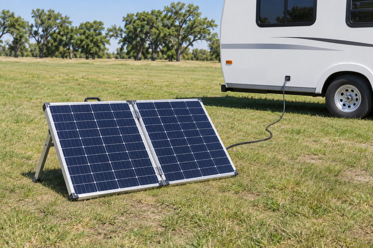
You have a folding panel, a socket marked “Zamp Solar Ready,” and two plugs that won’t mate. Before you buy a cable, find out where that socket goes. On one RV it takes power that’s ready to charge the battery. On another it takes raw solar power and sends it to a controller inside. The same panel can be a good match for one and the wrong choice for the other.
Which output does your port need?
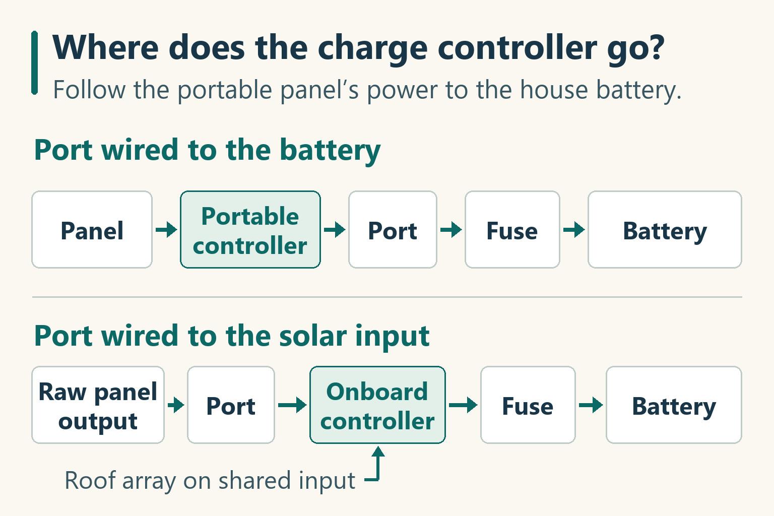
- Port wired to the house battery: use the battery output of a compatible solar charge controller. The controller can be built into the suitcase or installed between the panel and the port.
- Port wired to the solar input of an onboard controller: use the bare panel’s output or a factory-provided raw solar lead. Include any roof panels sharing that input when you check its limits.
- Unknown wiring: get the diagram for your RV’s year and model. A plug that fits, a solar display on the wall, or one voltage reading can’t tell you the whole route.
1. Find out where the sidewall port goes
Open the cap and photograph the socket face, its label and any part number. In the RV wiring diagram, follow the line marked portable solar or sidewall solar. Does it end at battery positive through a fuse or breaker, or at terminals marked PV+ and PV− on a solar controller? A roof array may have its own controller while the portable port goes straight to the battery.
The 2026 Airstream Basecamp manual (page 5-13) gives a useful example. Its front port takes a portable kit with its own controller set for the installed battery. The kit’s output must be 15 A or less, and Airstream places the 15 A port fuse in the battery box. Those figures belong to that trailer. Look for the equivalent entry in your manual before using them on yours.
Zamp’s two ATP sidewall diagrams show what to look for. In the battery-connected version, the red port wire passes through a fuse on its way to battery positive. In the solar-input version, the pair feeds the controller’s PV input. One drawing joins the roof and portable branches at a breaker and negative junction. The other connects the port directly to the controller’s solar terminals. If you can’t follow the pair and don’t have the right diagram, send the RV maker your VIN and port photo. Ask where the pair ends, which contact is positive and how much current the port allows. Have any undocumented modifications traced before plugging in.
2. Match the panel output to that wiring
Scroll sideways to see every column.
| Your portable panel | Port leads to battery | Port leads to PV input |
|---|---|---|
| Bare panel | Run the panel leads into a charge controller. Connect its battery output to the port. | Use the panel lead after checking the array limits below. |
| Suitcase with a controller and a separate raw-panel connection | Use its regulated battery lead. Check battery profile and port current limit. | Use the factory raw-panel lead or the bypass described for this kit. |
| Suitcase with only a fixed, regulated output | Use the regulated lead after checking its charging profile, polarity and output current. | Skip this port. Use the kit’s fused lead at the battery connection specified for the kit and RV, or choose a panel with raw output. |
Check the label beside the actual lead. On the Renogy suitcase with Voyager, the manufacturer’s drawing shows MC4-style plugs in three places: the pair coming off the panels, the Voyager’s PV input and the pair labeled for the battery. Trace the lead back to the PV or battery marking before choosing an adapter. Picking a lead by shape alone can put the controller on the wrong side of the socket.
For a battery-side port, compare the controller’s output settings with the battery maker’s charging limits. Find the battery-type menu on the controller or in its app, then look up the voltages for the selected profile. For LiFePO4, check equalization and cold-charge protection as well. If a fixed profile falls outside the battery’s limits, use a compatible controller or kit. Two independent controllers can charge one bank if their settings and combined charging current suit it. Keep the regulated lead off a solar-input port. A Victron SmartSolar 75/15, for example, starts only when the PV input exceeds battery voltage by more than 5 V. The suitcase’s battery lead is designed to charge a battery. Use raw panel output to feed the onboard controller.
3. Choose the cable and check the ratings
A Zamp SAE plug has one bare pin and one recessed contact inside a sleeve. Zamp identifies the covered contact on its kit plug as positive. Its mating RV port therefore has positive on the exposed pin. Some generic SAE leads fit the socket with the opposite polarity. If your port is the keyed ATP version, use the matching ATP cable. The “three-port” roof cap is something else again: it has three separate sockets for roof panels. Compare your photo with Go Power’s port guide before ordering.
- SAE kit lead: check the bag before buying an adapter. The Go Power DuraLite 100W kit comes with a controller and a Zamp Solar Ready connection for a battery-side port. An SAE polarity reverser swaps the two contacts. Use one only if the finished cable would otherwise join positive to negative and the lead is rated for the job.
- MC4 panel leads: for a bare panel feeding an SAE solar-input port, look for a matched MC4-to-SAE lead. For a battery-side port, the path is panel → portable controller → SAE battery lead → RV. If the suitcase has MC4-style plugs on its battery output, order the cable for that specific output and keep the fuse protection the kit requires. A panel adapter with the same-looking ends may be wired the other way. The panel maker’s accessory list is a good place to find a match. Stäubli’s MC4 instructions prohibit mating its connectors with another maker’s.
- Anderson, XT60 or barrel plug: look up the exact connector and what comes out of it. A folding panel sold for a power station may supply raw solar because the station contains the controller. If yours does, follow the bare-panel row above. The portable panel comparison (opens in a new tab) identifies which kits come with their own controller.
On the battery side, check the maximum charging current the kit can deliver through the port against the RV’s specification, cable and adapter ratings. Locate the factory protection for that positive branch. A fuse in the portable cable cannot protect the wire from the battery up to the outside socket. Look for the fuse or breaker near the battery and check its marking against the RV diagram. If you can’t identify it, have the branch checked. If protection is missing, have a correctly rated device fitted at the battery end before using the port. Never increase the factory fuse to accommodate a larger kit.
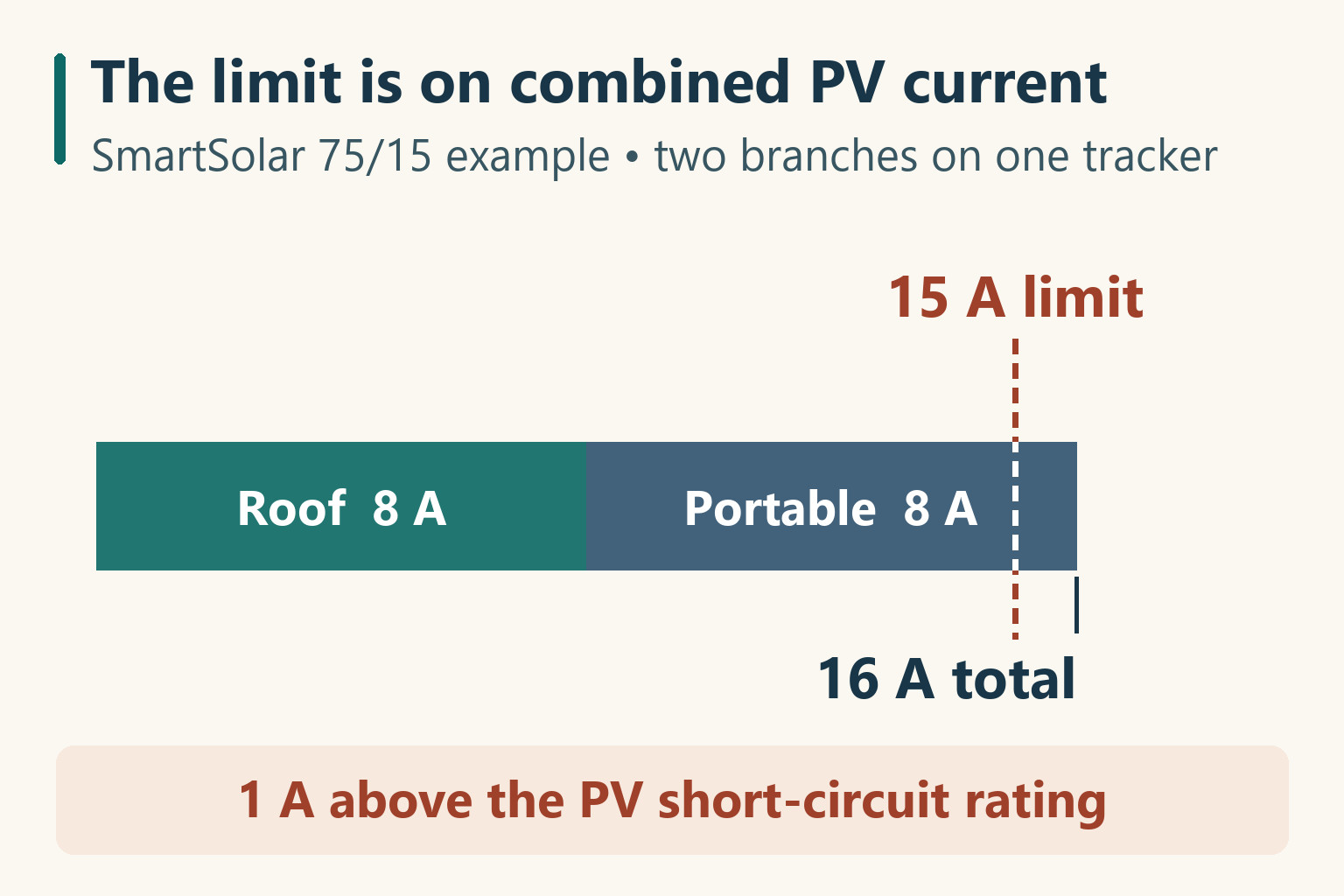
On the panel side, copy four values from the panel label: open-circuit voltage (Voc), operating voltage (Vmp), short-circuit current (Isc) and watts. If the port and roof feed the same tracker in parallel, add the Isc of each branch and compare the sum with the controller’s PV short-circuit limit. Check the cold-weather Voc of each string against its voltage ceiling and the total watts against its array-sizing policy. The branches should have similar Vmp. A 12 V-class panel plugged in alongside a roof string operating at twice its voltage may contribute little. The guide to matching roof and portable panels (opens in a new tab) explains that voltage mismatch. Check the portable branch against its own wire and connector ratings as well.
Take a Victron SmartSolar 75/15 on a 12 V bank. The specifications give 220 W nominal PV power, a 75 V ceiling and a 15 A limit on PV short-circuit current. An 8 A roof branch and an 8 A portable branch add up to 16 A. That combination fails the current check. The controller can limit excess power, but Victron warns that exceeding the Isc limit can damage it if the array is connected with reversed polarity. Choose a portable panel with a lower Isc, or give it its own controller and a separate fused battery connection. The controller sizing guide (opens in a new tab) works through the cold-voltage check.
4. Check which contacts will meet
Leave the kit unplugged. Identify positive on the socket and on the completed lead separately. On an SAE pair, one half’s bare pin enters the other half’s sleeve. Write down “pin” or “sleeve” for each positive contact. Left and right are easy to mix up the moment you turn the plug to face the RV.
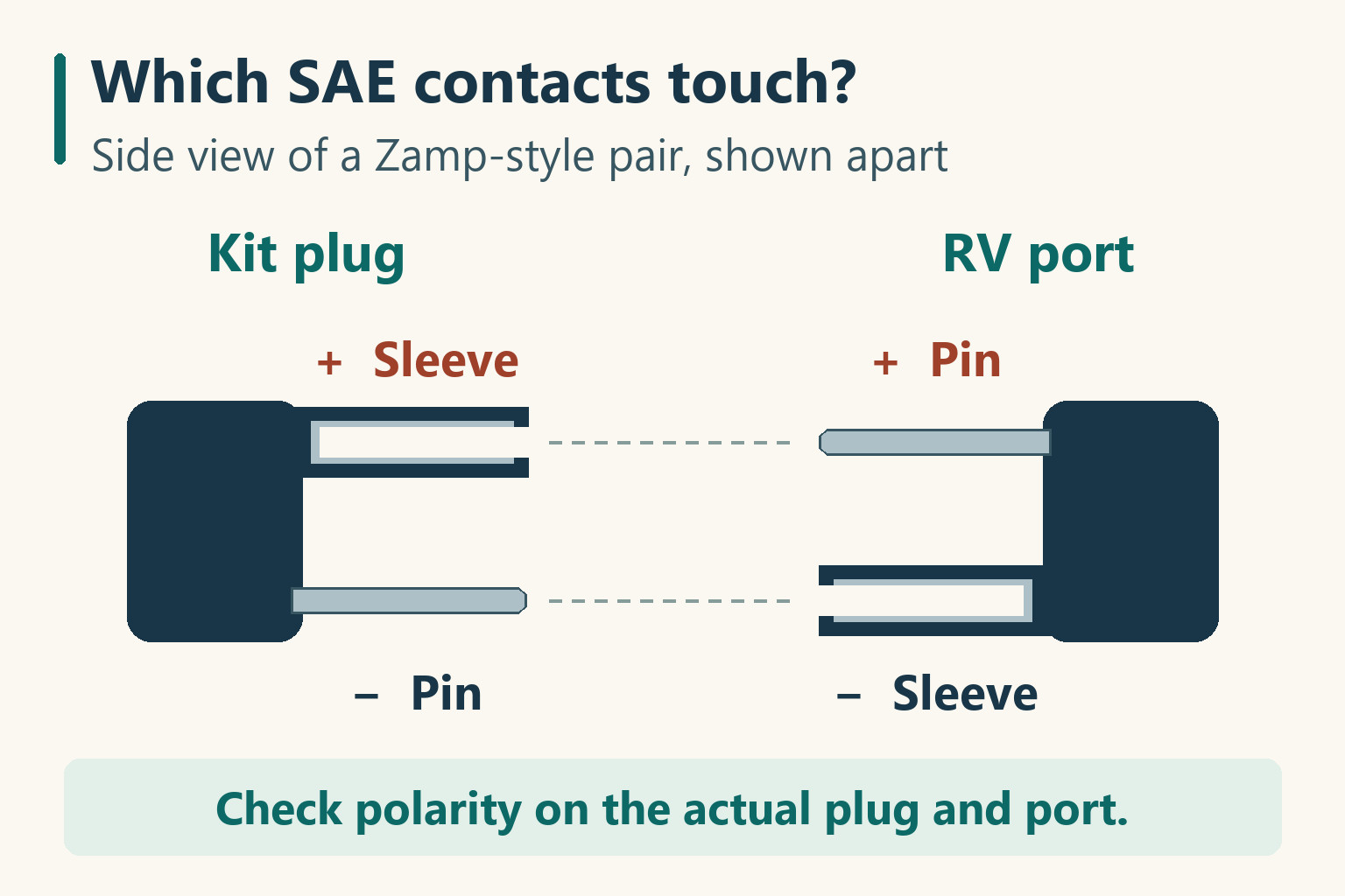
Known battery-connected port: select DC volts, with the black test lead in COM and red in V. Use insulated tips or a suitable mating test lead so you cannot bridge the contacts. With the red probe on one contact and black on the other, a positive battery-voltage reading identifies the red probe’s contact as positive. A minus sign means the positive contact is under the black probe. For a port wired to receive Zamp’s SAE plug, expect positive on the bare pin. Go Power labels its own side port pin-positive too. If your reading differs from the diagram, stop and identify the installed wiring. Never put a meter in amps mode across the port. Fluke shows the meter setup and how to read the sign.
Port sharing a solar input with the roof: sunlight on the roof can put the array’s voltage on the socket even when your portable panel is still in its bag. It can be well above battery voltage. If the expected range is known and your meter and insulated test lead are rated for it, the same DC-volts test identifies positive. For an unknown array, get the wiring identified before probing.
A reading of zero: possible causes include an open battery-branch fuse, a disconnect that cuts this circuit, or an isolated or dark PV source. Zero alone won’t identify the wiring or polarity. Check the diagram, fuse and switch positions. For a loose passive adapter, unplug both ends and use continuity mode to trace each contact to the marked positive or negative end. Fluke specifies a de-energized circuit for continuity testing. On installed wiring, isolate all sources, disconnect both ends of the run and verify absence of voltage before using that mode. If both ends aren’t safely accessible, have an RV shop identify the contacts.
At the panel end: a small bare panel with a known rating can show you which contact on the finished adapter is positive. Leave the RV unplugged. With the panel covered, fit matching insulated test leads rated for its cold Voc and select the meter’s DC voltage range. Expose the panel to light. A positive reading puts positive under the red probe, which should be on the contact that will meet the RV’s positive. Cover the panel again before removing the test leads. This is a polarity check. A colder panel can produce a higher open-circuit voltage than you measure today.
At a suitcase’s regulated output: a dark display or a zero reading can be normal before the controller sees a battery. The Renogy Voyager powers up from the battery side. Its detachable battery lead has a red positive clip. With the lead completely free of the battery and controller, use continuity to find the connector joined to that clip, then map the passive adapter the same way. If the cable is fixed and the kit doesn’t identify its contacts, get the pinout from the maker before connecting.
5. Connect and see what reaches the battery
Set the panel where it will stay put in the wind. Keep the cable clear of doors, slide-outs and feet, and check for wet or damaged contacts. At a battery-side port, leave PV isolated while you connect the portable controller’s battery lead. Check its battery voltage and charging profile, then bring the panel online. Victron specifies battery first for automatic voltage detection. For a Voyager suitcase delivered with its panels already connected, Renogy recommends blocking sunlight before attaching the battery lead.
At a solar-input port, first confirm the onboard controller has its battery supply and is set up for the bank. Isolate the PV sources feeding the connection, mate the raw-panel lead, then bring PV back online in the order specified for that installation.
When packing up, leave the MC4 joints together if the suitcase stores that way. Fully cover the portable panel and use the kit’s shutdown procedure to stop charging. On a controller with separate connections, isolate PV before removing its battery feed. On a shared PV port, isolate any roof branch that can feed the connection as well. A DC disconnect rated to interrupt the load can stop the current. Pulling an ordinary plug under load is no substitute. Only separate connectors once their required isolation and no-load conditions are met. If you can’t establish that, leave them mated. A battery-fed socket may still be live after unplugging. Close its cap.
With a portable controller, read its charging amps or zero a DC clamp meter and clamp it around one conductor on its battery-output lead. If the portable panel shares the roof controller, its display reports both panels together. While the bank is accepting charge, note the reading, fully shade the portable panel and compare again with roof sunlight and house loads steady. A drop shows it was contributing. An unchanged reading is inconclusive if the controller or battery was already limiting charge. Clamping one conductor on the portable PV branch tells you whether that panel contributes, but the amps there can differ from battery-side amps. A battery shunt shows the balance after house loads and other chargers. For example, 6 A delivered to the DC system with a 4 A fan running leaves about 2 A entering the bank if nothing else is supplying or drawing current. A nearly full battery may accept very little even in strong sun.
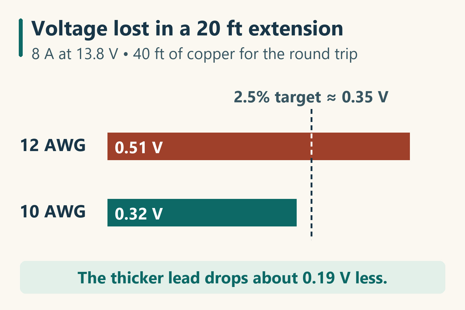
If an extension makes output worse, consider a 20 ft run of 12 AWG copper carrying 8 A. At roughly 0.0016 Ω per foot of conductor near room temperature, the 40 ft round trip drops 40 × 0.0016 × 8 = 0.512 V. That’s about 2.8% at an 18 V panel operating point or 3.7% on a 13.8 V charging lead. The watts lost in the same cable at 8 A are the same. On the charging lead, a controller sensing voltage at its own terminals can see 13.8 V while the battery gets only about 13.3 V. A 10 AWG run at about 0.0010 Ω per foot drops 0.32 V, or 2.3% of 13.8 V, within Victron’s roughly 2.5% design target. If a connector gets hot, stop and inspect it even if the cable calculation looks fine.
If charging still reads zero with a battery that should accept charge, start with the branch you just added. Check the port fuse, controller status and shaded cells before blaming the adapter. The solar charging troubleshooting guide (opens in a new tab) walks through where to measure next.
What people ask before plugging in
Do I always need an SAE polarity reverser?
No. For a port verified as Zamp-style with positive on its exposed pin, a matching lead has positive inside the sleeve. If your SAE lead instead puts positive on its pin, use a correctly rated reversing adapter or buy a lead wired for that port. Verify the assembled pair before connecting. A reverser on a lead that already matches introduces a fault.
Can the portable panel work while the rooftop solar is on?
Yes, if the installation supports both. On a shared controller, use the combined-array checks in step 3. If the portable kit charges through a separate controller, add the maximum charging currents of all sources that can run together and compare the total with the bank’s allowed charge current.
How many watts can a Zamp port take?
Start with the RV maker’s rating for that port. The 2026 Basecamp limits its front port to 15 A of regulated output. At 13.3 V, 15 A is about 200 W reaching the battery circuit. That figure doesn’t give a universal panel size. On a PV-input port, use the cold-voltage, short-circuit-current and array-power checks in step 3, including any roof panels on the same input. A fuse marking alone can’t tell you how many panel watts the system accepts.
Label the cable that worked
Tag the finished adapter with the RV it fits and what it carries: raw panel output or regulated charging power. Add the documented port current limit and, for a fused battery branch, its specified fuse rating. Next time you unpack the panel, you can pick the right lead without tracing the circuit again.
Spot an error or an outdated detail in this guide?
Report it