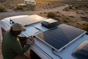
How to Install RV Solar Panels: Step-by-Step Guide
On this page
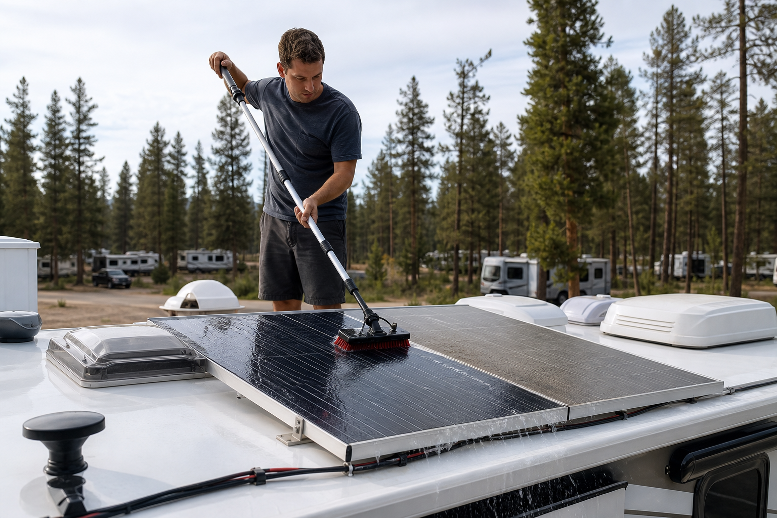
A rooftop solar install is five jobs done in order: plan where the panels go, fasten and seal them, bring the cable inside, wire the controller and fuses, and prove that the battery charges. This guide takes them one at a time, with a single worked example, two 200 W panels on a 12V battery bank, to show how the numbers on a panel’s datasheet decide the wiring, the controller and the fuses.
TL;DR
- The job in order: roof plan, mounting and sealing, cable entry, controller and fuses, then a charging check.
- Check four controller limits: maximum PV voltage against the panels’ cold open-circuit voltage, PV short-circuit current, charge current, and panel watts at your battery voltage.
- Battery first, panels last: and when you shut down, switch the panels off first with a DC breaker instead of pulling connectors.
- Size the battery side for the controller: the cable and fuse between controller and battery follow the controller’s rated output current, not the panel current.
- Butyl under, lap sealant over: then check the roof entry from inside after the first rain.
Before You Start
Settle three things before anything goes on the roof:
- The system is sized. Know your daily watt-hours from an RV energy audit, then size the panels and battery from that number; our RV solar sizing guide turns it into panel watts.
- The parts fit together. The panels’ voltage and current have to stay inside the controller’s limits, and the controller needs charge settings your battery accepts. The worked example below shows how to check.
- The roof is ready. Know the roof material (EPDM, TPO, fiberglass or aluminum), where the framing and wiring run underneath, which areas are safe to walk on, and what shades the roof during the day.
Work with a helper on the ladder, and keep the panels covered or their connectors apart while you wire, since a panel makes voltage as soon as light reaches it. Around the battery, use insulated tools and take off rings and watches.
Tools and Materials
- Mounting: the panel brackets, stainless fasteners that suit what’s under your roof, butyl tape, and self-leveling lap sealant rated for your roof membrane.
- Roof entry: a cable entry gland sized for your cable’s diameter.
- PV wiring: UV-rated PV cable, connectors of one brand and type, and the crimper made for them.
- Protection: a DC breaker or isolator for the panel line, and a fuse and holder for the battery line.
- Battery wiring: copper battery cable, lugs, a lug crimper, heat shrink, cable clamps and grommets.
- Tools: a drill with a depth stop, a torque wrench or torque screwdriver, a caulk gun, isopropyl alcohol and rags, a multimeter, and a clamp meter that can measure DC current.
Worked Example: Two 200 W Panels on a 12V Bank
Take two 200 W panels, each rated at 20 V and 10 A at maximum power, 24 V open circuit and 10.5 A short circuit, charging a 12V battery through an MPPT controller. These are round example figures at standard test conditions; your own panels’ datasheet gives the real ones. Wired two ways, the array looks like this:
Scroll sideways to see every column.
| Wiring | Operating Voltage | Operating Current | Open-Circuit Voltage | Cold Open-Circuit Voltage | Short-Circuit Current |
|---|---|---|---|---|---|
| Series | 40 V | 10 A | 48 V | About 53 V | 10.5 A |
| Parallel | 20 V | 20 A | 24 V | About 26.5 V | 21 A |
Panel voltage rises as the cells get colder. The cold column assumes 14°F (-10°C) and a temperature coefficient of -0.3 percent per °C, a typical value; use the coefficient on your panel’s datasheet and the coldest morning you expect.
Check the Controller’s Four Limits
A controller’s amp rating is only one of its limits. Hold the array against all four:
- Maximum PV voltage: compare it with the cold open-circuit voltage, not the label figure. The series array’s 53 V fits a 100 V controller with room to spare but would exceed a 50 V input.
- Maximum PV short-circuit current: the array’s short-circuit current, 10.5 A in series or 21 A in parallel, has to stay below it.
- Rated charge current: the most the controller delivers to the battery.
- Panel watts at your battery voltage: how much array the controller can turn into charge at 12V. Some makers allow more panel wattage than this as long as the voltage and current limits hold; the controller then caps its output.
Victron’s SmartSolar MPPT 100/30, for example, lists 100 V, 35 A of PV short-circuit current, 30 A of charge current and 440 W of panels at 12V, so either layout of the example array fits. Our charge controller sizing guide works through these limits for other arrays.
Series or Parallel?
In series, the current to the controller stays at 10 A, so a lighter cable can make the run, and the controller has plenty of voltage to work with. In parallel, the current doubles to 20 A and needs heavier cable, and the array’s operating voltage of about 20 V leaves a smaller margin over the battery, which shrinks further on hot days when panel voltage drops. Victron’s 100/30 starts when the PV voltage rises 5 V above the battery, then keeps charging while it stays at least 1 V above it, so check open-circuit voltage for startup and operating voltage for the charging margin. Parallel earns its place when a vent or AC shroud shades one panel for part of the day, because the unshaded panel keeps working on its own. On an open roof, series is usually the better choice.
The Battery Side Carries More Current
An MPPT controller trades voltage for current. At the battery, 400 W of panels becomes about 28 A at 14.4 V before losses, and up to the controller’s 30 A limit when the battery voltage is lower, even though the series array sends only 10 A down from the roof. So the cable from the controller to the battery, and its fuse, are sized for the controller’s rated output, not for the panel current: Victron specifies a 35 to 40 A fuse on the battery side of its 100/30. Pick that cable for both its current rating and the voltage drop over the whole run, positive and negative together, and make sure it can carry the current of the fuse that protects it.
Step 1: Plan the Roof Layout
Measure the roof and sketch it to scale, marking vents, AC shrouds, antennas, skylights and seams. Place the panels where nothing shades them through the middle of the day, and keep a clear path around the array so you can service the panels and seams later without stepping on them. Note where the rafters or backing run if you’ll screw into the roof, and where wiring runs underneath.
Then plan the cable. The roof entry should sit as close as practical to where the controller will go, and the controller belongs near the battery to keep the charging cable short. Pick series or parallel from the numbers above, and keep the sketch: it becomes your wiring record later.
Step 2: Mount and Seal the Panels
Screwed Brackets
Screwed brackets are the most common mount for framed panels. Fit the brackets to the panels on the ground, carry the panels up with a helper, and set them in place. Mark the holes, then check from inside what’s under each one before you drill: a hole should land on framing or backing that will hold the fastener, never on a seam, a wire run or an unknown cavity. Set the drill’s depth stop so the bit can’t punch through to the ceiling below.
Lay butyl tape under each bracket foot, drive the fasteners that suit your roof’s backing, and snug them down until the tape compresses evenly, without stripping the backing.
Drill-Free Mounts
Rigid panels don’t always need screws. Adhesive-bonded brackets hold framed panels too: Renogy’s corner brackets, for example, are bonded with Sikaflex 252 or a similar adhesive and are listed for flat aluminum, wood and fiberglass surfaces. The bond depends on the surface, its cleaning and the adhesive’s full cure, so follow the mount maker’s instructions exactly, and on a rubber membrane roof, confirm the mount and adhesive are approved for it first.
Flexible panels go on the way their maker specifies, with adhesive or with fasteners through their grommets. Because they lie flat on the roof, they run hotter than a framed panel on brackets and give up some output in summer heat.

Seal Every Fastener
On screwed mounts, the butyl tape under each foot is the main seal. Self-leveling lap sealant over the foot edges and screw heads is the second layer, keeping water off the butyl. Use a sealant your roof membrane’s maker approves, apply it to a clean, dry surface within the temperature range on the tube, and give it the time on the label before it sees rain. Lap sealant isn’t glue: a drill-free mount is held by the structural adhesive its maker specifies.
Step 3: Bring the Cable Inside
A roof entry gland made for your cable’s diameter gives the cleanest result. Before drilling, check from inside what’s below the spot, including wiring, framing and the ceiling liner, and set the drill depth to match. Drill, deburr the hole, feed the cables through, and seat and seal the gland as its instructions say. Leave a drip loop on the roof side so water runs off the cable before it reaches the gland, and clamp the cable so its weight never pulls on the gland or the connectors.
An existing chase, such as a refrigerator vent or a plumbing run, can save a hole, but only if the cable doesn’t block the fridge’s airflow or pass near the burner, flue or exhaust heat. Inside, fit grommets wherever the cable crosses a sharp edge, clamp it along the run, and label the positive and negative leads.
Step 4: Wire the Controller, Fuses and Battery
The current path runs like this:
Mount the Controller
Follow your controller’s manual for its position and clearances. Victron’s installation rules for its SmartSolar 100/30 are typical: mount it vertically with the terminals facing down, on a non-flammable surface, with at least 4 inches (10 cm) of clearance above and below, within about 10 feet (3 m) of the battery but never directly above it.
Fuses, Breakers and Disconnects
- Battery side. Put a fuse or breaker on the controller’s positive cable close to its source: at the battery, or at the bus bar if the controller is fed from one, in which case the cable from the battery to the bus bar still needs its own fuse near the battery. These fuses protect the cables from the battery’s short-circuit current, so they have to be DC-rated, rated for the system voltage, and able to interrupt the current your battery bank can deliver, which is high for lithium. Size the controller branch fuse from the controller manual and its cable rating; size the main battery fuse for the battery cable and the whole system.
- Panel side. One string, or two in parallel, normally needs no string fuses, as long as the reverse current one string can feed into the other stays within the panel’s maximum series fuse rating and the cable’s rating. When three or more strings run in parallel, the others can push more current into a faulted string than it’s built for, so each string usually needs its own fuse, sized no higher than the series fuse rating printed on the panel’s label. One shared fuse doesn’t do that job.
- PV disconnect. A breaker or isolator rated to switch DC under load at the array’s voltage and current, placed between the roof entry and the controller, lets you turn the panels off safely. Rate it above the array’s cold open-circuit voltage, and use it instead of pulling connectors, which can arc.
- Connectors. Many panels and cables come with connectors sold as MC4-compatible, but MC4 is Stäubli’s own product line, not a universal standard. Mate only connectors of the same brand and type, crimped with that maker’s tool; Stäubli warns that mixing brands raises contact resistance and can lead to failures.
- Grounding. Bond the panel frames, and the controller’s chassis terminal if it has one, to the RV chassis as the manuals describe. That’s separate from the PV wiring: Victron’s manual says neither PV positive nor PV negative should be grounded, and the battery-negative-to-chassis bond belongs at the system’s designated single point, on the system side of any monitoring shunt.
Our guide to sizing fuses and breakers walks through the ratings and placement.
Connect in the Right Order
Make all the connections first, with the circuits you’re working on isolated, then bring the system to life one side at a time. A panel’s own leads stay live in daylight even with the breaker open or a connector unplugged, so keep the array covered while you handle them.
- Isolate. Switch off or unplug every other charge source: the shore-power converter, generator, alternator charging and any existing solar. Leave the battery fuse out and the PV breaker open.
- Mark polarity. Identify positive and negative at the battery posts, and check and label both ends of every cable before it’s connected.
- Make the connections. Land the battery cables on the controller and at the battery or bus bar, then connect the cable from the PV breaker’s output to the controller’s PV terminals, and the array leads to the breaker’s input. Tighten each terminal to its maker’s torque: Victron gives 1.6 Nm for the battery and PV terminals on the 100/30, while battery posts and bus bars have their own values.
- Power the battery side. Insert the battery fuse or close its breaker. The controller starts up from the battery and detects the system voltage; Victron’s takes about 10 seconds. Confirm it shows 12V and the battery’s actual voltage.
- Set the charge profile. Enter the absorption and float voltages and the maximum charge current from your battery maker. Leave equalization off unless the maker calls for it, as lithium, AGM and gel batteries normally don’t, and turn off temperature compensation for LiFePO4. For cold weather, use the battery’s own low-temperature charge protection, or a controller with a compatible battery temperature sensor and a low-temperature cutoff enabled and set to the battery maker’s limit.
- Check the array. Uncover the panels and measure polarity and open-circuit voltage on the panel side of the open PV breaker. It should read positive and close to what your plan predicts, near 48 V for the series example on a cool, bright day.
- Close the PV breaker. In daylight, the controller should start charging shortly after.
To shut the system down, reverse the order: open the PV breaker first, then disconnect the battery. Our guide to connecting solar panels to an MPPT controller covers the terminal-by-terminal details.
Step 5: Check That It Charges
Prove the system works with numbers, on a clear day around midday:
- Read the controller. Note PV voltage and current, battery voltage and charge current, plus the time, the sky and the temperature. These readings are your baseline for later troubleshooting.
- Confirm with a clamp meter. Zero a DC-capable clamp meter with its jaws closed, then clamp it around one conductor only, positive or negative; around both, the currents cancel and it reads near zero.
- Expect different currents. With MPPT, the two sides don’t match: if the series array delivers 38 V at 8 A, about 300 W, the controller can deliver roughly 22 A on the battery side at 13.4 V, before the RV’s loads take their share.
- Read low current in context. A full battery in absorption or float accepts little current, so a low reading can be normal. The state of charge may also stay flat on a sunny day if your loads use as much as the panels make.
If something doesn’t add up:
- Unexpected or negative voltage at the panel leads: stop, and recheck polarity and every series or parallel connection before anything is connected to the controller.
- Panel voltage but no charging: the battery may be full, the panel voltage may sit too near the battery voltage, or the battery fuse may be open. Our RV solar troubleshooting guide goes through the checks in order.
Once the sealant has reached the water-exposure time on its label, gently hose-test the roof entry and mounts, or wait for the first rain, and check inside for moisture. Photograph the roof layout and the wiring with the labels visible; the photos save time whenever you trace a fault later.
Adding an Inverter
An inverter connects on the battery side, never to the controller’s LOAD output, which is made for small DC loads. Run it from the battery or from a bus bar fed by the battery, with its own fuse close to the source and cables sized for its full draw. If you have a shunt-based battery monitor, every negative cable except the battery’s own, including the inverter’s and the controller’s, lands on the system side of the shunt, or the monitor misses that current. Our guide to wiring an RV inverter covers sizing and the connection to the RV’s AC system.
After the Install
- After the first rain: check inside around the roof entry and under the mounts for any trace of moisture.
- Each season: look over the sealant for cracks or gaps and reseal with a compatible product, and check that no bracket has loosened.
- After the first trips: inspect the cable clamps and terminals. If a connection has loosened, isolate that circuit first, then tighten it to the torque in that component’s manual.
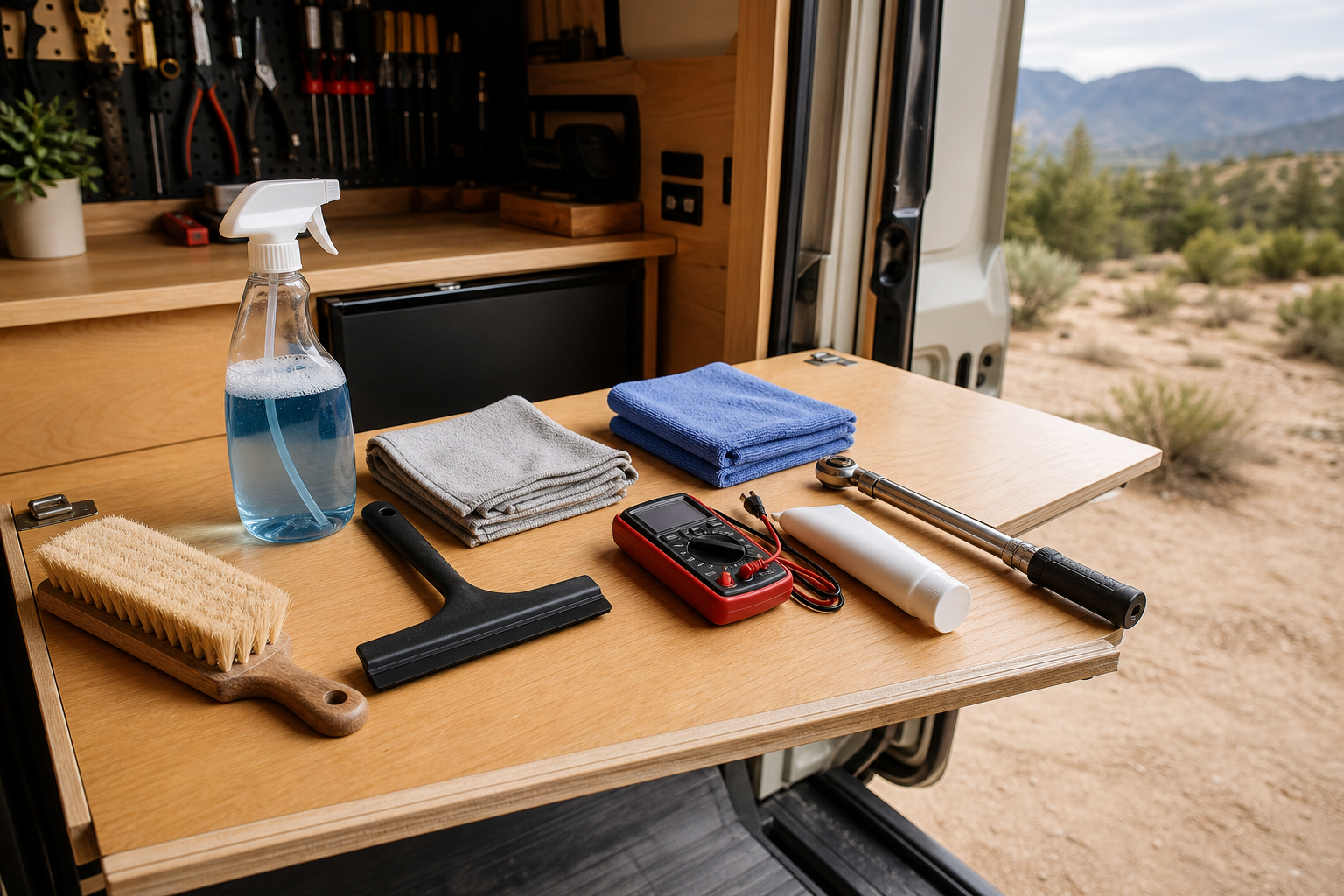
- When the panels get dusty: rinse them with plain water and a soft brush, early or late in the day when the glass is cool, and skip pressure washers and abrasive pads.
FAQs
- Can I install RV solar panels myself? Yes, if you’re comfortable working on the roof and with 12V DC wiring; a two-panel system is a realistic weekend project. Get an RV technician’s help with anything you can’t verify yourself, such as what’s under the roof where you plan to drill or how the RV’s existing charging is wired.
- Do I have to drill into the roof? Not for the panels: adhesive-bonded brackets and flexible panels can go on without screws where the roof surface suits them. The cable usually still needs one sealed roof entry, unless a factory solar prep port or an existing chase can take it safely.
- Can I use my RV’s factory solar prep? Often, yes. Find out what’s behind the port first: the wire size, its polarity, whether it runs to a controller or straight to the battery, and the panel wattage it was wired for. A prep run sized for one small panel can be too thin for a bigger array.
- What do I connect and disconnect first? Connect the battery first, then the panels, so the controller sees the battery before solar power arrives. To shut down, reverse it: switch the panels off at the PV breaker, then disconnect the battery.
- Can solar charge at the same time as my converter or another charger? Yes. Each charger regulates itself, so they can run together as long as each one is set for your battery and their combined current stays within the battery’s charge limit.
- Why does the controller show panel voltage but no charging? Usually the battery is already full, or the panel voltage isn’t far enough above the battery; Victron’s MPPT controllers need about 5 V more than the battery to start. Also check the battery fuse, the charge settings and any error code on the controller.
Conclusion
Plan the roof and the numbers first, and the rest of the install follows: brackets on solid backing and sealed in two layers, one clean roof entry, a controller whose four limits fit the array, a fuse close to the battery, and the battery connected before the panels. Then measure what the system does, keep the readings, and check the roof entry after the first rain.
Spot an error or an outdated detail in this guide?
Report it